Servomechanism Tuning
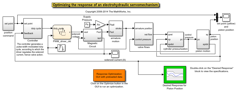
This example shows how to use Simulink® Design Optimization™ to optimize the position controller parameters for a servomotor piston. This model uses blocks from Stateflow®.
The controller sets the duty cycle of a pulse-width modulation circuit for the servomotor. The anti-windup controller Proportional and Integral gains are tuned to optimize the step response characteristics of the servomotor.
Open the servo_demo model using the command below and run the simulation. The simulation produces an unoptimized position of the piston and the initial data for optimization.
open_system('servo_demo')

There are two Scope blocks in the model. Double-click the set point(yellow) and piston position Scope block to view the set-point and the unoptimized position of the piston.
Double-click the solenoid current(A) Scope block to view the output solenoid current of Magnetic Circuit.
Double-click the Desired Response for Piston Position block to view constraints on the position of the piston.
You can launch the Response Optimizer using the Apps menu in the Simulink toolstrip, or the sdotool command in MATLAB®. You can launch a pre-configured optimization task in the Response Optimizer by first opening the model and by double-clicking on the orange block at the bottom of the model. From the Response Optimizer, press the Plot Model Response button to simulate the model and show how well the initial design satisfies the design requirements.

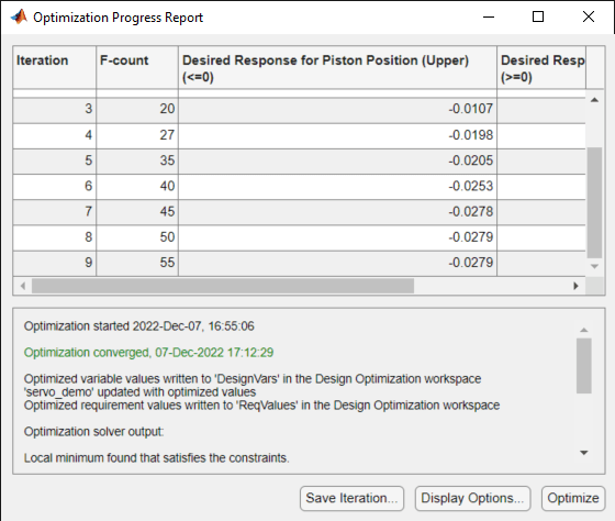
We start the optimization by pressing the Optimize button from the Response Optimizer. The plots are updated to indicate that the design requirements are now satisfied.


The plot shows the final optimized piston position.