Access Model Data Wirelessly by Using Observers
Observers allow you to monitor the dynamic response of your system model while preserving the system model design and system result integrity. Observers use two types of blocks, Observer Reference blocks and Observer Port blocks. The Observer Reference block wirelessly links a system model to an Observer model, which contains verification logic. Inside an Observer model, you use Observer Port blocks to access data from the system model to drive the verification logic.

The types of Simulink® signals and model data you can observe are:
Continuous-time and Discrete-time signals
Zero-order hold signals
Scalar signals
Wide signals
Nonvirtual bus signals
Messages
Conditional subsystem signals
Custom code global variables used by a C Caller block, in addition to the above signals
FMU block internal variables, in addition to the above signals
Stateflow® local data parameters, except locals, parameters, signals, and other data defined in a Simulink subsystem inside a Stateflow state.
Stateflow state self activity, except if that activity is in a Simulink subsystem inside a Stateflow state.
C Function and S Function **what in them?**
Observer Reference Block
Observer Reference blocks wirelessly link a system model to an Observer model. Observer Reference blocks can only be at the top level of a system model and do not have input or output ports. You map your Simulink signals or other model data to the Observer Port blocks that are contained within the Observer model. Once you map the Observer Port blocks to a signal or data, you can connect the ports to the verification subsystem within the Observer model. Running your system model also runs the linked Observer model.
Wireless access allows you to use observers to monitor your system model without causing changes to the system. Observers allow you to create a clear differentiation between your system design and verification subsystems.
Add an Observer Reference Block
The Observer Reference block references
a separate verification model that you use to
verify your system model. To add an
Observer Reference block to your
system model, first, in the Simulink toolstrip,
open Apps and click Simulink Test in the Model
Verification, Validation, and Test section. Click
Add Observer Reference in
the Tests tab. Alternately,
right-click the top level of your Simulink canvas. To add the Simulink Test app
options to the menu, point to Select
Apps and click the Simulink Test button
![]() . Then, in the
Simulink Test app section, click the Add Observer
Reference block button
. Then, in the
Simulink Test app section, click the Add Observer
Reference block button ![]() . An Observer
Reference block is added to your system
model, and an Observer model is created and
opened. You must save the Observer model in a
writable folder on the MATLAB® path.
. An Observer
Reference block is added to your system
model, and an Observer model is created and
opened. You must save the Observer model in a
writable folder on the MATLAB® path.

Connect an Existing Observer Model
To connect an Observer Reference block
to an Observer model that you have already
created, first save your Observer model in a
writable folder on the MATLAB path. Next, right-click the
Observer Reference block, and then
click the Block Parameters button
![]() .
.

Enter the name of the Observer model that you want to connect to your system and select Apply. When you double-click your Observer Reference block, your Observer model opens in a new window.
Create an Observer Model from Signals or Other Model Data
To create an Observer model that is mapped to a signal
line or observable data in your model, select one
or more signals or the data that you want to
observe. Then, click Add Observer
Reference in the
Tests tab. Alternately,
right-click the signal or data and in the Simulink
Test app section ![]() select Observe Selected
Signals > New Observer. Simulink creates an Observer model and adds
an Observer Reference block to your
system model.
select Observe Selected
Signals > New Observer. Simulink creates an Observer model and adds
an Observer Reference block to your
system model.
Connect Signals or Other Model Data Using an Observer Port Block
Each Observer model contains one or more Observer Port blocks. After mapping an Observer Port block to a model object or signal within a system model, the Observer Port block outputs the same output as its mapped object or signal. A new Observer Port block shows a line through the signal symbol, signifying that the block is not mapped to any signal or object.
![]()
Access the Manage Observer Dialog Box
To map an Observer Port block to a signal or object in your system model, open the Manage Observer dialog box using one of these methods:
In the Tests tab, click Manage Observer.
Click the gear in the lower-right corner of the Observer Reference block.
Right-click the Observer Reference block, and in the Simulink Test app section
 , select Manage This
Observer Reference.
, select Manage This
Observer Reference.In the Observer model, double-click an Observer Port block.

Using the Manage Observer dialog box you can:
Filter and select signals and objects for observation
Add, remove, or configure Observer Port blocks
Trace signals and objects between observer ports and models
On the left side of the Manage Observer dialog box is the Observable Area panel. The Observable Area panel displays the block hierarchy and observable outputs of your model. Observed signals or objects appear bold in the hierarchy.
The right side of the Manage Observer dialog box shows the Observer panel. The Observer panel displays the block hierarchy, including Observer ports in the Observer Reference block. An Observer Port block that is mapped to a signal or object appears bold and displays the signal to which it is attached. Once the Observer Port is mapped to a signal or object, its block icon updates to show that the Observer Port is attached to a signal or object.

To view the full path of an observed object, point to an Observer Port block.
If you change the name of an observed signal or object in your system model, the Observer Reference block updates the name of the output signal from the Observer Port block. If a signal is not named and does not have a label, the output of the Observer Port block is set to an empty string.
Map an Observer Port Block to a Signal or Object
To map a signal or object to an Observer
Port block, open the Manage Observer
dialog box. In the Observable Area panel, select
the signal or object that you want to observe. To
map the signal or object to a new Observer
Port block, double-click the selected item
or click the Add New Observer Port icon
![]() . To map the signal
or object to an existing Observer
Port block, select the Observer Port in
the Observer panel and click the Reconfigure
Observer Port icon
. To map the signal
or object to an existing Observer
Port block, select the Observer Port in
the Observer panel and click the Reconfigure
Observer Port icon
![]() . In the Observer
model, you can then connect the output from the
Observer Port to a verification subsystem to test
your results.
. In the Observer
model, you can then connect the output from the
Observer Port to a verification subsystem to test
your results.
Trace Observed Items to Model Signals and Objects
You can trace observed items and their observer ports within the Manage Observer dialog box. You can also trace items between the Manage Observer dialog box and the system model, and between the system model and the Observer model.
To trace an observed item to its observer port within the Manage Observer dialog box, use one of these methods:
Double-click on the ObserverPort item in the Observer panel. The observed item is highlighted in the Observable Area panel.
Right-click on the ObserverPort item in the Observer panel and select Show in left panel. The observed item is highlighted in the Observable Area panel.
To trace an observed item or observer port between the Manage Observer dialog box and the system model, use one of these methods:
Right-click on the ObserverPort item in the Observer panel or in the Observable Area panel and select Show in model. The observed item is highlighted in the model.
Right-click on the observed signal or object in the system model, and in the Simulink Test app section
select Go to Linked
Observer Ports. The associated Observer Ports are
highlighted in the Observer model.
To trace an observer port and observed item between the system model and the Observer model, use one of these methods:
Right-click on the Observer Port in the Observer model, and in the Simulink Test app section
select Go to
observed <item type>. The observed signal or
object is highlighted in the system model.Right-click on the observed signal or object in the system model, and in the Simulink Test app section
select Go to Linked
Observer Ports. The associated Observer Ports are
highlighted in the Observer model.
Simulate a System Model with an Observer Reference Block
The Observer model is used to monitor signals in your system model and check that your system model is running within specified parameters. With or without an Observer Reference block, your system model simulation results are the same. The Observer Reference block does not affect the compilation of your system model.
Note
Both the system model and Observer model must run in normal simulation mode. Both models can run at fixed-step or variable-step rate, or one model can run at fixed rate and the other at variable rate. The two models can also use the same or different solvers. See Choose a Solver.
Create Observers for Heat Pump Temperature Model
This example shows how to use Observer Reference and Observer Port blocks to wirelessly observe signals. In this system, the plant is modeled using Simulink, and the controller is modeled using Stateflow. The goal of the example is to monitor both the temperature of the heat pump and when the pump is cooling or heating the room. The direction in which the fan is blowing indicates cooling or heating. The data name is pump_dir, and it is connected to port 3 in the Stateflow chart.
Open the Model
sltestHeatpumpExample

Create the Observer Model and Observer Reference Block
1. In the Apps tab of the model, click Simulink Test in the Model Verification, Validation, and Test section. The Tests tab opens
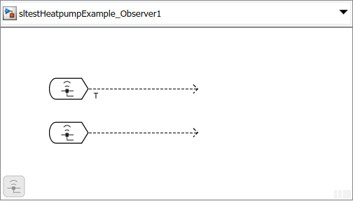
2. In the Tests tab, click Add Observer Reference. Simulink adds an Observer Reference block to your system model and creates an Observer model called sltestHeatpumpExample_Observer1.
Create and Map Observer Port Blocks
1. In the main model, open the Plant subsystem and right-click the signal T. To add the Simulink Test app options to the menu, point to Select Apps and click the Simulink Test button ![]() . Then, in the Simulink Test app section, select Observe Select Signals > New Observer. The Observer model adds an Observer Port block that is mapped to signal T.
. Then, in the Simulink Test app section, select Observe Select Signals > New Observer. The Observer model adds an Observer Port block that is mapped to signal T.
2. Save the new Observer model.
3. In the Tests tab of the Observer model, click Add Observer Port to add another Observer Port block. Double-click the new ObserverPort1 block to open the Manage Observer dialog box. In the Observer panel, the second Observer Port, ObserverPort1, is listed below the first port.
4. To map ObserverPort1 to the Simulink data pump_dir, click ObserverPort1. In the Observable Area panel, expand Controller and controller_chart, and select Outport3. Click the Reconfigure icon between the two panels. The ObserverPort1 name updates to ObserverPort1 (controller_chart:3).

5. The Observer Port blocks are in the Observer model and are now mapped and ready to be connected to Scope blocks or a Verification Subsystem (Simulink Design Verifier). If you want to implement a verification subsystem, see the Temperature Condition States section of Refine, Test, and Debug a Subsystem for information about conditions to test.
Copyright 2022 The MathWorks, Inc.
Convert Verification Subsystem to an Observer Reference
Converting a Verification
Subsystem (Simulink Design Verifier) to an Observer Reference block
is a way to declutter a system model. Select the subsystem
to convert and, in the Tests tab, click
Send to Observer.
Alternately, right-click the verification subsystem, and in
the Simulink Test app section ![]() , select Move selected block to
Observer > New Observer. This operation cannot be undone.
, select Move selected block to
Observer > New Observer. This operation cannot be undone.
This model contains the Verification Subsystem, Safety Properties.

By converting the Safety Properties Verification Subsystem to an Observer Reference block, you remove the signals that link the verification subsystem to the system model while preserving the ability to test the integrity of the system.

The two signals, throt and
output1, are automatically
mapped to two Observer Port blocks in the
Observer model,
sltestBasicCruiseControlHarnessModel_Observer1.

Observer Considerations and Limitations
Model Simulation and Compilation
An Observer model does not simulate if:
The Observer model contains root-level Inport or Outport blocks.
The Observer model is a library or subsystem reference model.
Standalone compiling of observer models is not supported.
Observer Reference and Observer Port Blocks
Observer Reference blocks are ignored during simulation if:
You use any simulation mode other than normal mode (for example, accelerator, SIL/PIL).
You are generating code.
The Observer Reference block is in a model reference hierarchy. Observer Reference blocks are supported only at the root of the top model.
The Observer Reference block is in an Observer model. Recursion of Observer models is not supported.
Observer Port blocks do not support:
Signals between System Composer™ components.
Signals from root Inport blocks in referenced models that connect to blocks without direct-feedthrough inputs. To observe the signal, connect the signal to a block with direct-feedthrough inputs. For more information on blocks with and without direct-feedthrough inputs, see Direct-Feedthrough Input Impact on Execution Order.
Data Export and Output
Logging signals or data store memory and saving final operating points are supported for Observers. All other data export options, such as time, state, output, final state, and save to file, are not supported.
To Workspace and Dashboard blocks in Observers are not supported and do not produce output.
Mismatched Settings Between the Observer and Design Model
When these settings in the Observer model differ from the settings in the design model, the design model settings are used and the Observer model settings are ignored.
Data import or export settings
Coverage settings
Solver stop time
See Also
Observer Port | Observer Reference | sltest.observer.observeElement