Read Serial Data from GPS Shield Using Arduino Hardware
This example shows how to use Simulink® Support Package for Arduino® Hardware to receive serial data from a GPS shield on the Arduino hardware.
Supported Hardware
Arduino Mega 2560
Arduino Mega ADK
Arduino Due
Arduino Leonardo
Arduino MKR1000
Arduino MKR WIFI 1010
Arduino MKR ZERO
Arduino Nano 33 IoT
Arduino Nano 33 BLE Sense
Arduino-derived boards having more than one serial port
Introduction
In this example, the Simulink models arduino_serial_gps and arduino_serial_gps_standalone are used to explain how to decode raw National Marine Electronics Association (NMEA) data from a GPS shield on an Arduino hardware.
NMEA Data from GPS Receiver on GPS Shield
The NMEA format is a specification that defines how data is transmitted between various marine electronic devices. GPS receiver, a marine electronic device, also transmits data in NMEA format. The data is transmitted in a sequence called a sentence. Each sentence contains information, such as latitude, longitude, speed, and time, as ASCII characters. A sentence can have a maximum of 80 characters. Each sentence is independent of other sentences from the receiver.
NMEA Sentence Format

    NMEA Header          | Value                               | Description
  _ _ _ _ _ _ _ _ _ _ _ _ _ _ _ _ _ _ _ _ _ _ _ _ _ _ _ _ _ _ _ _ _ _ _ _ _ _ _ _  _ _ _ _ _ _ _ _ _ _ _ _ _ _ _ _ _  _ _ _ _ _ _ _ _ _ _ _ _ _ _ _ _ _
    StartChar            | $                                   | ASCII for 36
    SentenceName         | For example, GPGGA                  | NMEA Sentence Identifier
    Separator            | ,                                   | ASCII for 44
    Data_1 to Data_N     | For example, 083445.00,1256.60109,N | Data fields, such as latitude and longitude
    CheckChar            | *                                   | ASCII for 42
    CheckSum             | For example, 7E                     | Hexadecimal number representing 8-bit exclusive OR
                         |                                     | of all characters between $ and *
    EndChar              | CR                                  | Carriage return
The u-blox Neo-6M GPS shield, used in this example, supports six types of NMEA sentences: $GPGSV, $GPGLL, $GPRMC, $GPVTG, $GPGGA, and $GPGSA. This example focuses on how to decode $GPGGA and $GPRMC NMEA sentences from the u-blox Neo-6M GPS shield on Arduino.
$GPGGA NMEA Sentence Nomenclature

$GPRMC NMEA Sentence Nomenclature

Required Hardware
To run this example, you must have the following hardware:
Supported Arduino board
GPS antenna
USB cable
Connecting wires
Step 1: Connect GPS Shield, GPS Antenna, and Arduino Hardware
Note: Before you start with this example, we recommend you complete the following:
1. Connect the pins on the u-blox NEO-6M GPS shield to the pins on your Arduino Mega 2560 board as shown in this table.
   u-blox NEO-6M GPS shield pin   | Arduino Mega 2560 pin
 _ _ _ _ _ _ _ _ _ _ _ _ _ _ _ _ _ _ _ _ _ _ _ _ _ _ _ _ _ _ _ _
      5V                          |  5V
      GND                         |  GND
      Vin                         |  Vin
      3V                          |  3V
      RX    (pin 1)               |  TX1    (pin 18)
      TX    (pin 2)               |  RX1    (pin 19)
Note: If you are using any other Arduino board, the pin numbers that correspond to TX1 and RX1 pins on Arduino are different.

2. Connect the GPS antenna to the GPS shield.
3. Connect the Arduino board to your computer using a USB cable.
Wait for the GPS Fix LED on the GPS shield to start glowing. A glowing LED indicates that the GPS shield is acquiring satellite signals. Signals are acquired easily in locations that have a clear view of the sky. If you are using the shield for the first time, the shield might take a few minutes to acquire signals.
Step 2: Configure Serial Receive Block
This section explains how to configure the Serial Receive block to receive raw serial NMEA sentences from the GPS shield.
1. Open the arduino_serial_gps Simulink model.
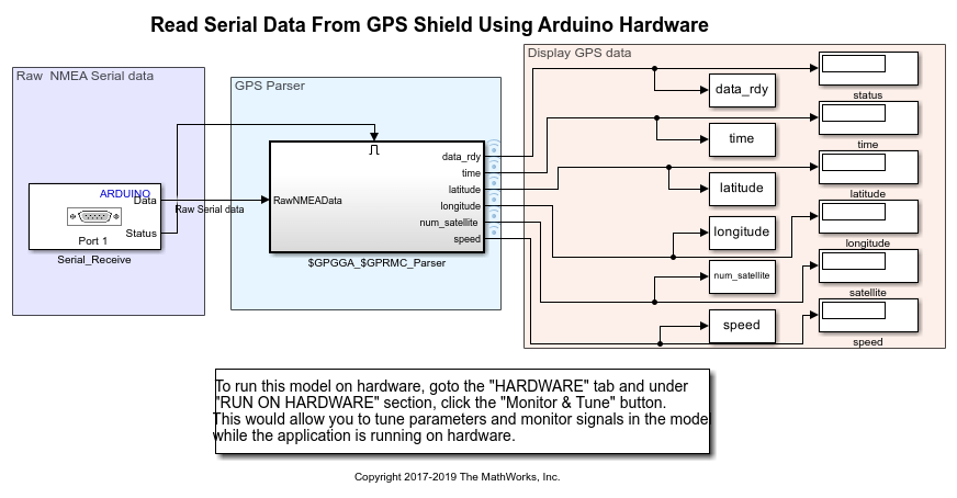
This model is configured to run in External mode. In this model, the GPS Shield sends data to the Serial port 1 of the Arduino hardware. The received data is stored in MATLAB® Workspace variables.
Step 3: View Source Code of Decode Algorithm
To view the MATLAB System object™ source code of the decoding algorithm:
1. Double-click the GPS Parser block. This block is a custom block created using MATLAB System.
The block decodes raw NMEA sentences from the Serial Receive block using a decoding algorithm. The block outputs fields, such as status, time, latitude, longitude, and speed, from NMEA sentences.
The Output when disabled parameter in all the Outport blocks, data_rdy, time, latitude, longitude, and num_satellite, is set to reset. Selecting this option ensures that this block output values only when the $GPGGA_$GPRMC_Parser subsystem is enabled. If the subsystem is disabled, the block outputs 0.
2. In the Block Parameters dialog box, click the Source code link. The code:
a. Specifies NMEA sentence properties, such as StartChar and EndChar.
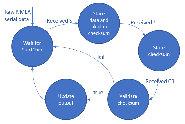
b. Uses the gps_parser.cpp and gps_parser.h| files. The beginning sections of these files explain the implementation of the decoding algorithm. The model uses the decoding algorithm to decode NMEA sentences from the GPS shield. This state diagram describes the decoding algorithm.
Step 4: Configure Simulink Model for Arduino Hardware
Note: If the u-blox Neo-6M GPS shield is connected to your Arduino Mega 2560 board using Serial port 1, you can skip this section.
1. To configure the model, click the Model Configuration Parameters button on the Simulink toolbar.
2. In the Configurations Parameters dialog box, select Hardware Implementation.
3. From the Hardware board list, select the type of Arduino board that you are using.
4. From the Groups list under Target hardware resources, select Serial port properties.
5. Set a baud rate of the serial port to which the GPS shield is connected. In this example, the Serial 1 baud rate parameter is set because the TX1 and RX1 pins connected to the GPS shield correspond to Serial port 1 of Arduino Mega 2650.
6. Select a baud rate that is same as the baud rate of the GPS shield. The baud rate of the GPS shield used in this example is 9600.
7. Click Apply. Click OK to close the dialog box.
Step 5: Run Simulink Model in External Mode (Monitor and Tune)
On the Hardware tab of the Simulink model, in the Mode section, select Run on board and then click Monitor & Tune. The lower left corner of the model window displays status while Simulink prepares, downloads, and runs the model on the hardware.
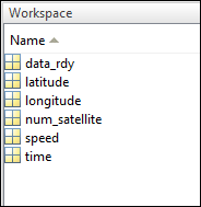
The TX pin of the GPS shield transmits raw NMEA sentences to the RX1 pin of the Arduino hardware. The algorithm decodes the data and stores the data in MATLAB Workspace variables data_rdy, time, latitude, longitude, num_satellite, and speed.
Note: If no data is received in MATLAB Workspace variables, verify the following:
The TX and RX pins of the GPS shield are connected to Arduino properly.
The GPS Fix LED on the GPS shield is still glowing.
Step 6: Deploy Simulink Model on Arduino Hardware
1. Open the arduino_serial_gps_standalone Simulink model.

In this model, the GPS Shield sends data to the Serial port 1 of the Arduino hardware. Arduino sends data to your computer over Serial port 0 (USB port). You can view the received data on any serial terminal in your computer. The models provided in this example are preconfigured for the Arduino Mega 2560 board. You can run these models on any of the boards listed in the Supported Hardware section by changing the Hardware board parameter in the Simulink model. For more information on how to change the Hardware board parameter, see the Step 4: Configure Simulink Model for Arduino Hardware section of this example.
2. In this model:
a. Double-click the GPS Parser block and select the NMEA fields to be displayed on the serial terminal. In this example, the GPS Parser block decodes only the latitude field of the NMEA sentence.
b. Double-click the Serial Transmit block and verify these parameter values:
     Parameter   | Value         | Description
 _ _ _ _ _ _ _ _ _ _ _ _ _ _ _ _ _ _ _ _ _ _ _ _ _ _ _ _ _ _ _ _ _ _ _ _ _ _ _ _ _ _ _ _ _ _ _ _ _ _ _ _ _ _ _ _ _ _ _ _ _ _ _ _ _ _ _ _ _ _ _ _ _ _
Send mode | println | Add a carriage return character '\r'(ASCII 13) and
| | a newline character '\n'(ASCII 10) after every NMEA sentence.
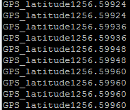
Label | GPS_latitude | The label of the data that you want to print.
Format | Decimal | The format in which you want to print the data.
Precision | 5 | The precision value for the Decimal data format.The Serial Transmit subsystem is enabled only when the status port of the $GPGGA_$GPRMC_Parser subsystem outputs |1|.
3. In the Configurations Parameters dialog box, go to Hardware Implementation > Target hardware resources > Groups > Serial port properties, and observe that the Serial 0 baud rate is set to 9600.
4. On the Hardware tab of the Simulink model, in the Mode section, select Run on board and then click Build, Deploy & Start. The lower left corner of the model window displays status while Simulink prepares, downloads, and runs the model on the hardware. Wait for the model to start running on the hardware.
The TX pin of the GPS shield transmits raw NMEA sentences to the RX1 pin of the Arduino hardware. The algorithm decodes the data and sends the data to the serial terminal on your computer.
5. Open the serial terminal on your computer (for example, Arduino IDE serial monitor).
When logging in to the serial terminal:
Specify the COM port number that corresponds to your serial connection. To learn how to find the COM port number, see Manually Configure COM Port and Bootloader on Host.
Specify the baud rate same as the baud rate set in the Model Configuration Parameters dialog box. In this example, the baud rate is
9600.
After you login, you can see that the latitude coordinates are displayed with label 'GPS_latitude' on the serial terminal.
Other Things to Try
Using the same models, modify the
gps_parser.cppandgps_parser.hfiles to decode other types of NMEA sentences, such as $GPGSV and $GPGLL.Create a model to decode messages from other sensors that follow a similar message format.
Select a Web Site
Choose a web site to get translated content where available and see local events and offers. Based on your location, we recommend that you select: United States.
You can also select a web site from the following list
Americas
- América Latina (Español)
- Canada (English)
- United States (English)
Europe
- Belgium (English)
- Denmark (English)
- Deutschland (Deutsch)
- España (Español)
- Finland (English)
- France (Français)
- Ireland (English)
- Italia (Italiano)
- Luxembourg (English)
- Netherlands (English)
- Norway (English)
- Österreich (Deutsch)
- Portugal (English)
- Sweden (English)
- Switzerland
- United Kingdom (English)