Attitude Control for X-Configuration Quadcopter Using External Input
This example shows how to use the UAV Toolbox Support Package for PX4® Autopilots to design an attitude controller for an X-configuration quadcopter that uses input from a joystick or radio control transmitter. In this example, you also verify the controller design using PX4 Host Target and SIH in Host Target simulator.
Introduction
UAV Toolbox Support Package for PX4 Autopilots enables you use Simulink® to design flight controller algorithm to stabilize the vehicle based on the current vehicle attitude and track the desired attitude using Simulink.
In this example, you will learn how to use the PX4 Host Target with SIH simulator and jMAVSim visualizer to design as well as verify the attitude controller for quadrotor vehicle. You will also learn how to control the vehicle using joystick or radio control transmitter. The jMAVSim simulator which is part of the Software In The Loop (SITL) simulation as defined in PX4 website, is installed as part of the support package installation.
Prerequisites
If you are new to Simulink, watch the Simulink Quick Start video.
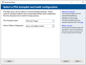
Perform the initial setup and configuration tasks of the support package using Hardware Setup screens. In the Hardware Setup screen Select a PX4 Autopilot and build configuration, select PX4 Host Target as the Hardware board from the drop-down list.
Install the ground control station software - QGroundControl.
Required Hardware
To run this example, you will need the following hardware:
Either a Joystick (for example, Logitech F310 Gamepad) or a Radio control transmitter (for example, FlySky FS-i6)
Model
Open the px4demo_AttitudeControllerJoystick model.
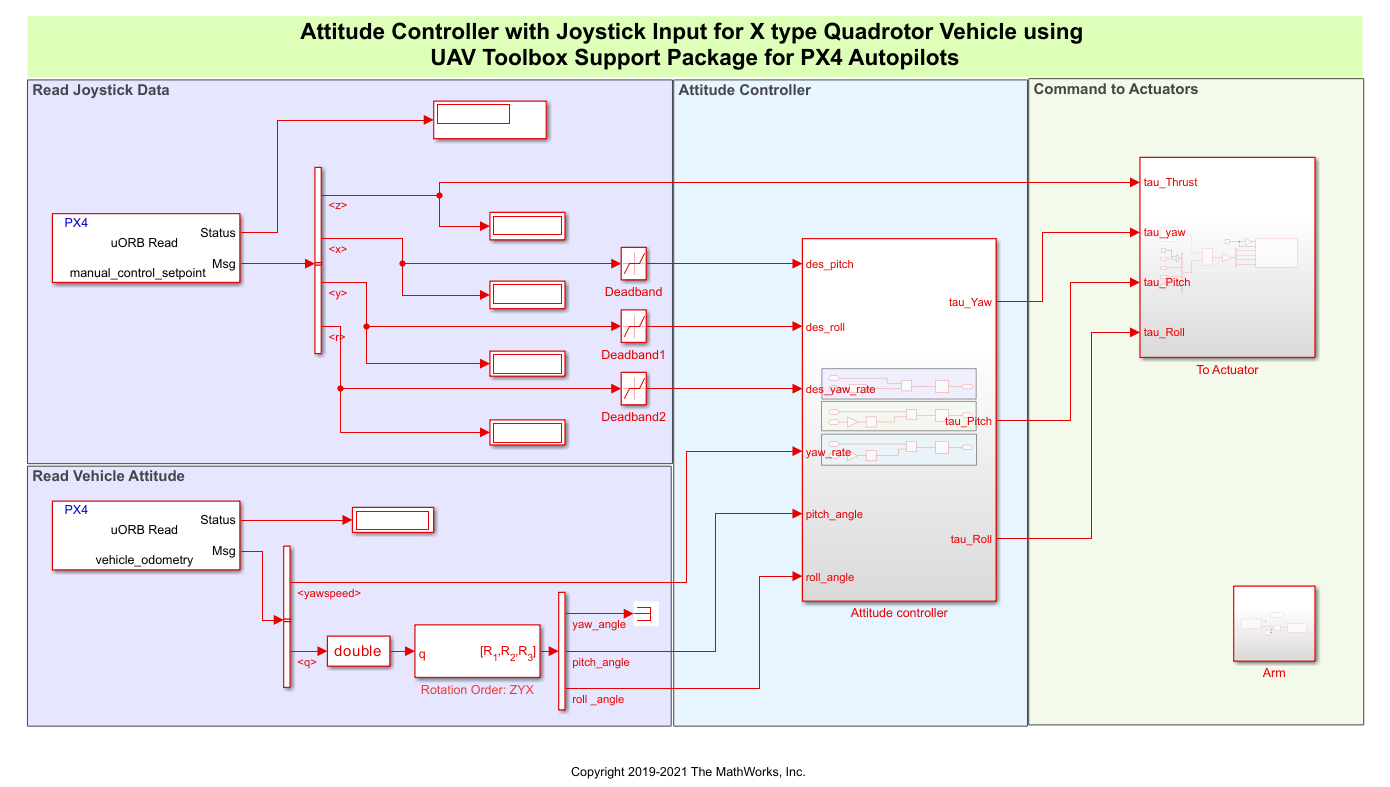
The model implements a Proportional-Integral-Derivative (PID) controller to control the attitude of an X type quadrotor aerial vehicle. At each time step, the algorithm adjusts rotational speeds of different rotors to track the desired attitude, based on input from the joystick or radio control transmitter.
Task 1 - Configure the Model to Read Input from Joystick or Radio Control Transmitter
In this task, you configure the model to obtain the stick position of the joystick or radio control transmitter. This is implemented by using the uORB Read block, which is configured to read the message manual_control_setpoint.
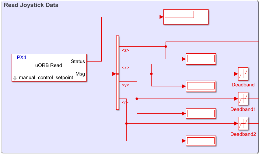
Note: The joystick data in uORB message manual_control_setpoint is only available after QGroundControl is running and connected to PX4 Host Target.
Task 2 - Read Vehicle Attitude and Design Attitude Controller Using PID 1Dof
In this task, you configure the model to read the vehicle attitude and obtain the required values (pitch, roll, and yaw) and design an attitude controller using the PID 1Dof block in Simulink.
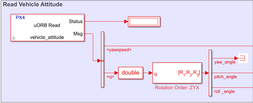
Use a uORB Read block, which is configured to read the message
vehicle_attitude, to access the vehicle's current attitude.
Use the Quaternions to Rotation Angles block to convert attitude quaternion to various Euler rotation angles (pitch, roll, and yaw) according to selected rotation order.
In the Attitude Controller subsystem, use three PID 1Dof blocks to generate the required angular rates from the difference between the desired value (as read from the joystick) and the current attitude value.
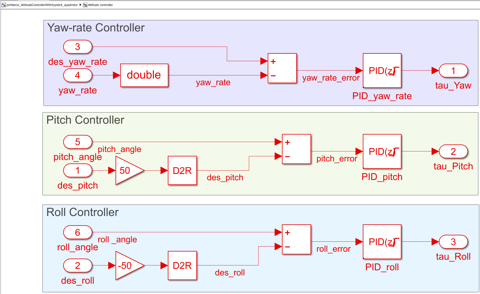
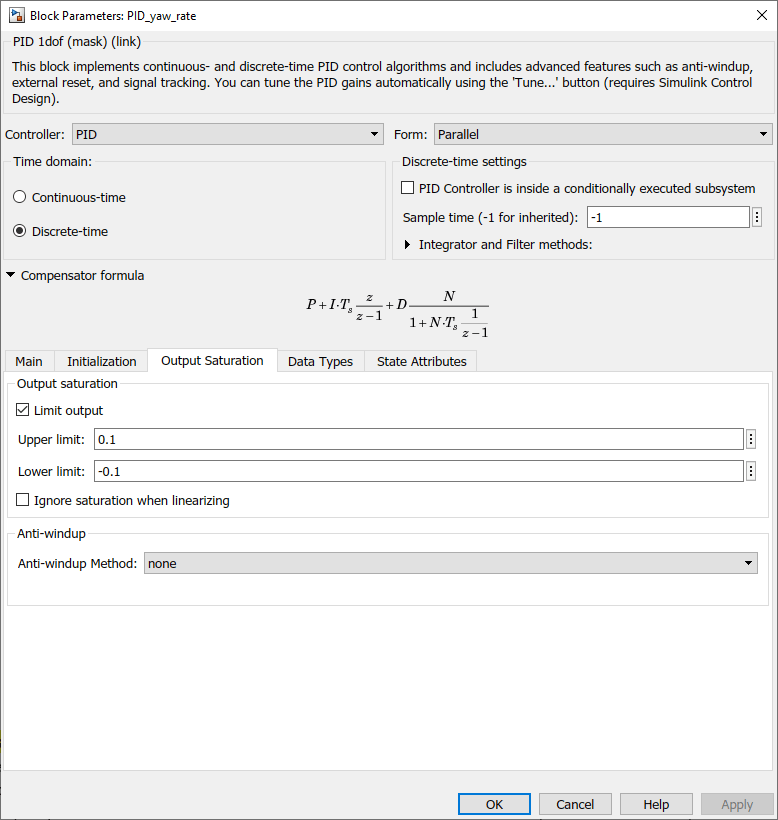
The output of each PID 1Dof block is restricted between predefined maximum and minimum values to limit the rate at which rotation angles change.
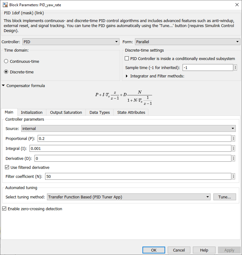
Each PID 1Dof block uses filtered derivatives to eliminate the amplification of any undesired noise signal due to signal differentiation.
This figure shows the settings in the Main tab of the PID 1Dof block mask.
Task 3 - Combine Angular Rate Demands to Generate Rotational Speed of Individual Rotor
In this task, you configure the model to generate the individual rotational speed of each of the four rotors from current angular rate demands and also based on the total thrust requirement from the throttle stick.
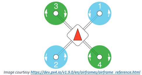
The input from the throttle stick of the joystick or radio control transmitter is the base value of the rotational speed of all the rotors. According to the angular rate demands, a small fraction is added to or subtracted from the base value.
For this example, the motor configuration is as shown in the following figure.
Select Actuator Output Type
In the Simulink model, click Select Actuator Output Type and then select the required option to use PX4 mixers or Simulink mixers from the Actuator Output Type dialog box.

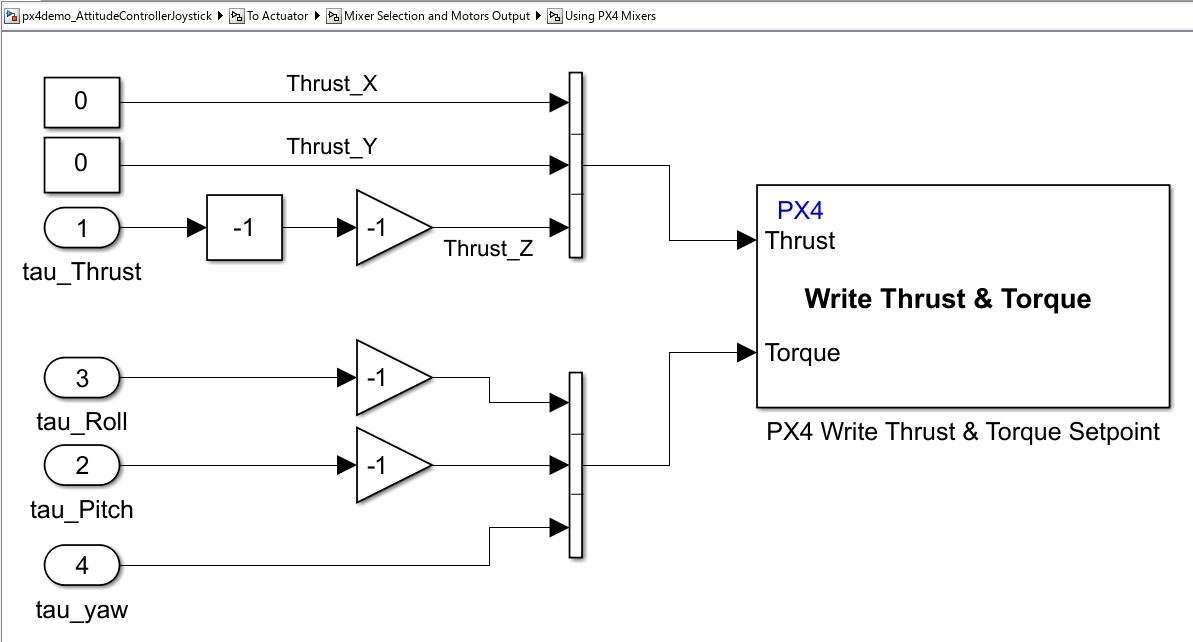
Using PX4 Mixers
If you select Write Thrust & Torque Setpoint (Using PX4 Mixers) option, then the Using PX4 Mixers subsystem contains a PX4 Write Thrust & Torque Setpoint block and the airframe configurations will be defined in QGC and used by PX4 for mixing.
To use PX4 mixers as the actuator output type, you must configure these settings in QGC.
1. In the QGC, select Airframe.

Navigate to Setup > Airframes.
Select
SIH Quadcopter X. Click Apply and Restart on top-right of the Airframe Setup page.
Restart QGC to apply the changes.
2. Click Actuators and select the required actuators.

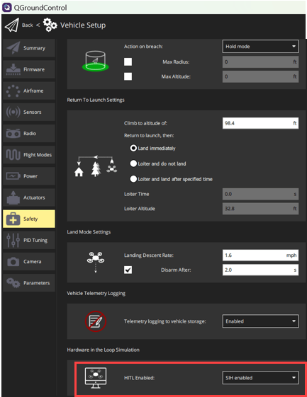
3. Navigate to Setup > Safety section.
4. Click Comm Links and configure the communication links. For more information see Configuring QGC for Vehicle Visualization Without a Display.

5. Arm the vehicle by moving the slider.

Select SIH enabled from the HITL Enabled list.
Using Mixer in Simulink
The Using Mixer in Simulink subsystem in the model contains a Mixer matrix block, which is defined in Simulink. The structure of the mixer matrix depends on the arrangement of motors with respect to the frame of reference.

The PX4 Actuator Write block takes the individual rotational speed values and sends it to a particular actuator. Along with rotational speeds, the block also has input field for Arm.
Task 4 - Run the Model on PX4 Host Target and Start jMAVSim Simulator
In this task, you select the Hardware Board as PX4 Host Target and start the jMAVSim simulator.
1. In the Modeling tab, click Model Settings.
2. In the Configuration Parameters dialog box, navigate to the Hardware Implementation pane.
Set the Hardware board to PX4 Host Target (the same option that you selected during Hardware Setup screens).
In the Target Hardware Resources section, set the Build options to Build, load and run.
3. Once Simulink model is ready, there are two options to build the Simulink model and launch the simulator:
On the Hardware tab, in the Mode section, select Run on board and then click Build, Deploy & Start. Once the model is deployed in the target hardware (PX4 Host Target in this example), the jMAVSim simulator is launched and the model executes independently in target hardware without having any dependencies and without communication with Simulink.
On the Hardware tab, in the Mode section, select Run on board and then click Monitor & Tune. The jMAVSim simulator is launched and you can monitor and log the data while the model executes in the target hardware.
During Monitor and Tune operation, various parameters and variables can be monitored using display or scope blocks.
Task 5 - Connecting Joystick or Radio Control Transmitter to Host Computer and Configuring QGroundControl
While performing simulation using the PX4 Host Target and the jMAVSim simulator, you can connect external input devices to QGroundControl, which transmits commands (joystick movement and button presses) to PX4 Autopilot using MAVLink.
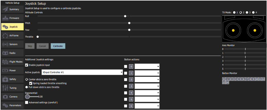
Connecting Joystick
While the model is running on PX4 Host Target, connect a joystick to the host computer and configure the joystick using QGroundControl. In this example, we use Logitech F310 Gamepad. The below figure shows the configuration settings in QGroundControl, required for the joystick.
Connecting Radio Control Transmitter
While the model is running on the PX4 Host Target, connect a radio control transmitter to the host computer using different interfaces provided by various manufacturers. In this example, we use FlySky FS-i6 radio control transmitter.
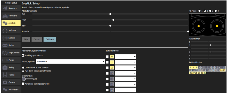
The FlySky FS-i6 can be connected to the host computer's microphone input port using a trainer cable. An external software utility such as SmartPropoPlus can be used to generate a virtual joystick device, which mimics the behavior of joystick while taking stick inputs from radio control transmitter.
Create a virtual joystick, connect the radio control transmitter to the host computer, and while the model is running on PX4 Host Target, configure the joystick using QGroundControl. The below figure shows the configuration settings in QGroundControl, required for the radio control transmitter.
For further understanding of how the joystick is connected with QGroundControl and how QGroundControl communicates joystick values to PX4 Host Target, refer to this page.
Task 6 - Analyze Response to Inputs from Joystick or Radio Control Transmitter
Once the configuration is done correctly, the data based on position of joystick is available in the uORB message manual_control_setpoint.
The response of the simulated vehicle to the various inputs are as follows:
Throttle stick input corresponds to rate at which the quadrotor vehicle climbs or descends. The default quadrotor vehicle of jMAVSim simulator hovers at around 50% of throttle input (that is, 1500us actuator output).
If the throttle stick input is more than the input required for hovering, the vehicle gains the altitude and the climb rate is proportional to the positive difference between actual throttle applied and throttle required for hover.
If the throttle stick input is less than input required for hovering, the vehicle loses the altitude and the descend rate is proportional to the negative difference between actual throttle applied and throttle required for hover as well as the height from which vehicle starts the descend.
Pitch and roll stick inputs corresponds to pitch and roll angle of the vehicle respectively. Center stick results in a level flight with zero pitch / roll. Depending on the direction of stick, the pitch / roll angle increases or decreases linearly up to the maximum limit, which is set at 50 degrees for this example. The maximum limit of pitch / roll angle is usually inferred from vehicle characteristics, and for a more agile vehicle, it can be higher.
Yaw stick input corresponds to the rate at which the yaw angle increases or decreases. When the yaw stick is kept centered, the yaw angle remains constant. Depending on the direction of stick, the angle increases or decreases.
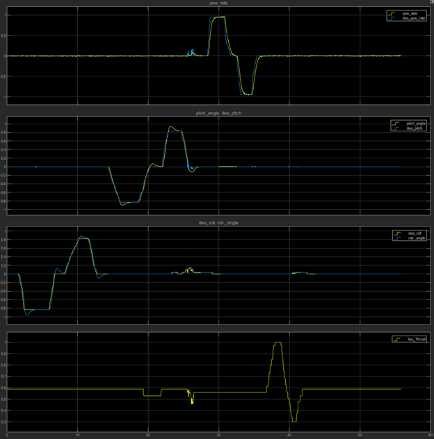
If you use the Monitor and Tune option to run the model on PX4 Host Target (as explained in Task 4), you can use real-time data logging. This is helpful while tuning PID controllers for a desired response. The below figure shows Simulink viewer which is configured to monitor current values of vehicle attitude and applied input. The figure indicates that the PX4 Autopilot is able to follow applied input in all three rotational axes.
To log various variables into the MATLAB® workspace, the ToWorkspace block of Simulink can be used. For configuration of logging parameters during the Monitor and Tune operation, refer to Set External Mode Properties for Logging to Workspace.
For more information about tuning PID controllers for attitude control, see the example Position Tracking for X-Configuration Quadcopter.
Select a Web Site
Choose a web site to get translated content where available and see local events and offers. Based on your location, we recommend that you select: United States.
You can also select a web site from the following list
Americas
- América Latina (Español)
- Canada (English)
- United States (English)
Europe
- Belgium (English)
- Denmark (English)
- Deutschland (Deutsch)
- España (Español)
- Finland (English)
- France (Français)
- Ireland (English)
- Italia (Italiano)
- Luxembourg (English)
- Netherlands (English)
- Norway (English)
- Österreich (Deutsch)
- Portugal (English)
- Sweden (English)
- Switzerland
- United Kingdom (English)