Channel I/O
The RF chip of your radio hardware determines the number of channels you can use for sending and receiving data.
| Radio Hardware | RF Chip | Number of Channels |
|---|---|---|
USRP™ E310 USRP E312 | AD9361 | 2 |
Channel I/O Using AD9361
You can send or receive data using a single channel or you can use both channels.
Transmit Data on Single Channel Using System Object
Create a transmitter System object™ for the USRP E3xx embedded series radio hardware.
tx = sdrtx('E3xx', ...
           'IPAddress','192.168.3.2', ...
           'CenterFrequency',2.4e9, ...
           'BasebandSampleRate',1e6);
Set channel mapping to
1to specify single channel use on channel 1. Alternatively, you can also specify single channel use on channel 2 by setting the channel mapping to2.tx.ChannelMapping = 1;
Create a DPSK modulator System object to modulate the transmitted signals.
mod = comm.DPSKModulator('BitInput',true);Transmit data. Because only one channel is in use, the number of columns in
modSignalis also1.for counter = 1:20 data = randi([0 1],30,1); modSignal = mod(data); tx(modSignal); end
Release the System object.
release(tx);
Transmit Data on Single Channel Using Simulink Block
This model is set up to transmit data on a single channel. The Channel mapping parameter of the E3xx Transmitter block is set to 1. The underflow port is disabled by clearing the Enable output port for underflow indicator parameter. The Sine Wave block is configured to generate a 1 kHz sine wave, sampled at 1 MHz. When you run this model, the E3xx Transmitter block sends the generated sine wave through the air. You can inspect the generated data in the Spectrum Analyzer.
![]()
Receive Data on Single Channel Using System Object
Create a receiver System object for the USRP E3xx embedded series radio hardware.
rx = sdrrx('E3xx');Set the channel mapping to indicate that only channel 1 is in use.
rx.ChannelMapping = 1;
Receive data. Because only one channel is in use, the number of columns returned in
datais also1.[data,validData,overflow] = rx();
Release the System object.
release(rx);
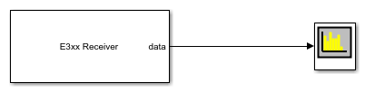
Receive Data on Single Channel Using Simulink Block
This model is set up to receive data on a single channel. The Channel mapping parameter of the E3xx Receiver block is set to 1. The overflow port is disabled by clearing the Enable output port for overflow indicator parameter. The output data type is set to double. When you run this model, the connected Spectrum Analyzer displays the data noise received through the air. To generate an output tone, explore the Loopback parameter options on the Advanced tab. To generate a sine wave, set the Test signal injection parameter to Tone Inject Rx and the Signal generator mode to Tone.
Transmit Data on Multiple Channels Using System Object
Create a transmitter System object for the USRP E3xx embedded series radio hardware.
tx = sdrtx('E3xx', ...
           'IPAddress','192.168.3.2', ...
           'CenterFrequency',2.4e9, ...
           'BasebandSampleRate',1e6);
Set the channel mapping to
[1 2]to indicate that both channels are in use.tx.ChannelMapping = [1 2];
Create a DPSK modulator System object to modulate the transmitted signals.
mod = comm.DPSKModulator('BitInput',true);Transmit data. Because two channels are in use, duplicate
modSignalto form a two-column vector.for i = 1:5 data = randi([0 1],30,1); modSignal = mod(data); tx([modSignal modSignal]); end
Release the System object.
release(tx);
Transmit Data on Multiple Channels Using Simulink Block
This model is set up to transmit data on two channels. The Channel mapping parameter of the E3xx Transmitter block is set to [1 2]. The underflow port is disabled by clearing the Enable output port for underflow indicator parameter. The Sine Wave Channel 1 block is configured to generate an 8 kHz sine wave. The Sine Wave Channel 2 block is configured to generate a 1 kHz sine wave. Both sine waves are sampled at 1 MHz. When you run this model, the E3xx Transmitter block sends the generated and combined sine waves through the air. You can inspect the generated data in the Spectrum Analyzer blocks.
![]()
Receive Data on Multiple Channels Using System Object
Create a receiver System object for the USRP E3xx embedded series radio hardware.
rx = sdrrx('E3xx');Set channel mapping to
[1 2]to indicate the number of channels in use.rx.ChannelMapping = [1 2];
Receive data. Because multiple channels are being used, the number of columns returned in
datais also 2.[data,validData,overflow] = rx();
Release the System object.
release(rx);
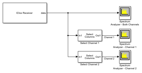
Receive Data on Multiple Channels Using Simulink Block
This model is set up to receive data on two channels. The Channel mapping parameter of the E3xx Receiver block is set to [1 2]. The overflow port is disabled by clearing the Enable output port for overflow indicator parameter. The output data type is set to double. When you run this model, the connected Spectrum Analyzer blocks display the data noise received from the air through each channel. To generate an output tone, explore the Loopback parameter options on the Advanced tab. To generate a sine wave, set the Test signal injection parameter to Tone Inject Rx and the Signal generator mode to Tone. These settings apply to both channels.
See Also
Topics
Select a Web Site
Choose a web site to get translated content where available and see local events and offers. Based on your location, we recommend that you select: United States.
You can also select a web site from the following list
Americas
- América Latina (Español)
- Canada (English)
- United States (English)
Europe
- Belgium (English)
- Denmark (English)
- Deutschland (Deutsch)
- España (Español)
- Finland (English)
- France (Français)
- Ireland (English)
- Italia (Italiano)
- Luxembourg (English)
- Netherlands (English)
- Norway (English)
- Österreich (Deutsch)
- Portugal (English)
- Sweden (English)
- Switzerland
- United Kingdom (English)