Read Distance Using VL53L4CD ToF Sensor Over I2C with ArduPilot Autopilot
R2026bThis example shows how to read distance measurements from a VL53L4CD time-of-flight (ToF) sensor connected to an ArduPilot autopilot over I2C. The model uses the I2C Controller Read and I2C Controller Write blocks from the UAV Toolbox Support Package for ArduPilot Autopilots to initialize the sensor, read range data, and decode the measurement status. You can use this sensor configuration for applications such as low-altitude obstacle detection, precision landing height measurement, or terrain-following flight modes.
The VL53L4CD sensor communicates over I2C and returns range data through internal registers. In this example, the Simulink model performs these tasks:
Configures the VL53L4CD sensor during model initialization.
Writes register addresses to the sensor before each read transaction.
Reads raw range data from the sensor over I2C.
Converts the returned bytes to a distance value in millimeters.
Reads and decodes the sensor range status.
Prerequisites
1. If you are new to Simulink, watch the Simulink Quick Start video.
2. If you have not done so already, complete the steps in Install UAV Toolbox Support Package for ArduPilot Autopilots in Windows.
Hardware Connection
Connect the VL53L4CD sensor to the I2C bus of the ArduPilot autopilot.The wiring must include:
SDA
SCL
Power
Ground
The default I2C peripheral address of the VL53L4CD is 0x29. Verify that this address matches the configuration in the model I2C blocks.
If your hardware platform exposes multiple I2C buses, make sure that the selected bus in the model matches the physical bus you use on the board.
Open Model
Open the ArduPilotVL53L4CDRead.slx model.
modelName = "ArduPilotVL53L4CDRead";
open_system(modelName)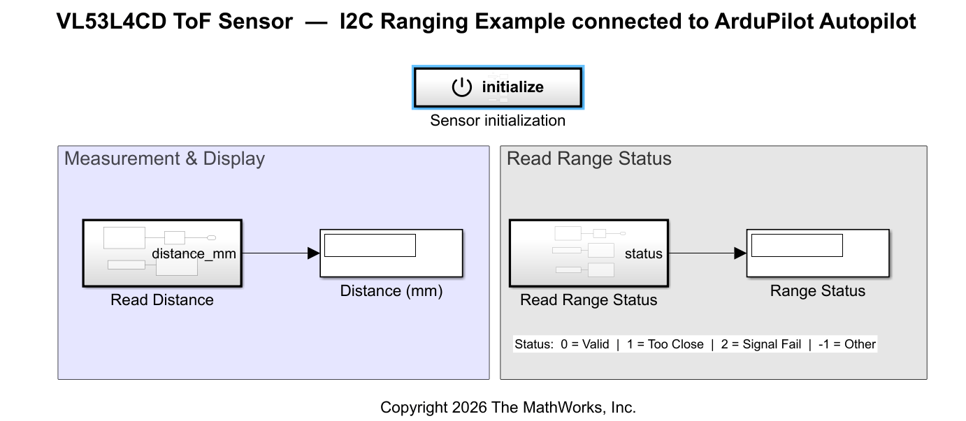
Model Overview
The model organizes the I2C communication workflow into three subsystems: Sensor Initialization, Read Distance, and Read Range Status. All I2C blocks are configured with the sensor peripheral address 0x29.
Sensor Initialization Subsystem
The Sensor Initialization subsystem configures the VL53L4CD sensor once at model start. An event-based trigger executes the following I2C write sequence:
Write_Config — Writes the default sensor configuration payload.
Reset_Enter — Sends the reset-enter command.
Set_Meas_Rate — Configures the inter-measurement timing period.
Start_Ranging — Sends the start-ranging command.
Reset_Exit — Sends the reset-exit command.
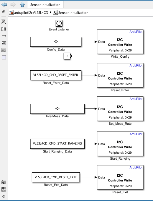
After initialization completes, the sensor begins autonomous ranging and the model enters its measurement loop.
Read Distance Subsystem
The Read Distance subsystem performs a register-based I2C read each time step:
SetPointer — An I2C Controller Write block writes the target register address to set the sensor internal register pointer.
ReadData — An I2C Controller Read block reads the corresponding data bytes from the sensor.
Bytes_to_mm — A MATLAB Function block converts the raw bytes into a distance value in millimeters.
The subsystem outputs the converted measurement as distance_mm.
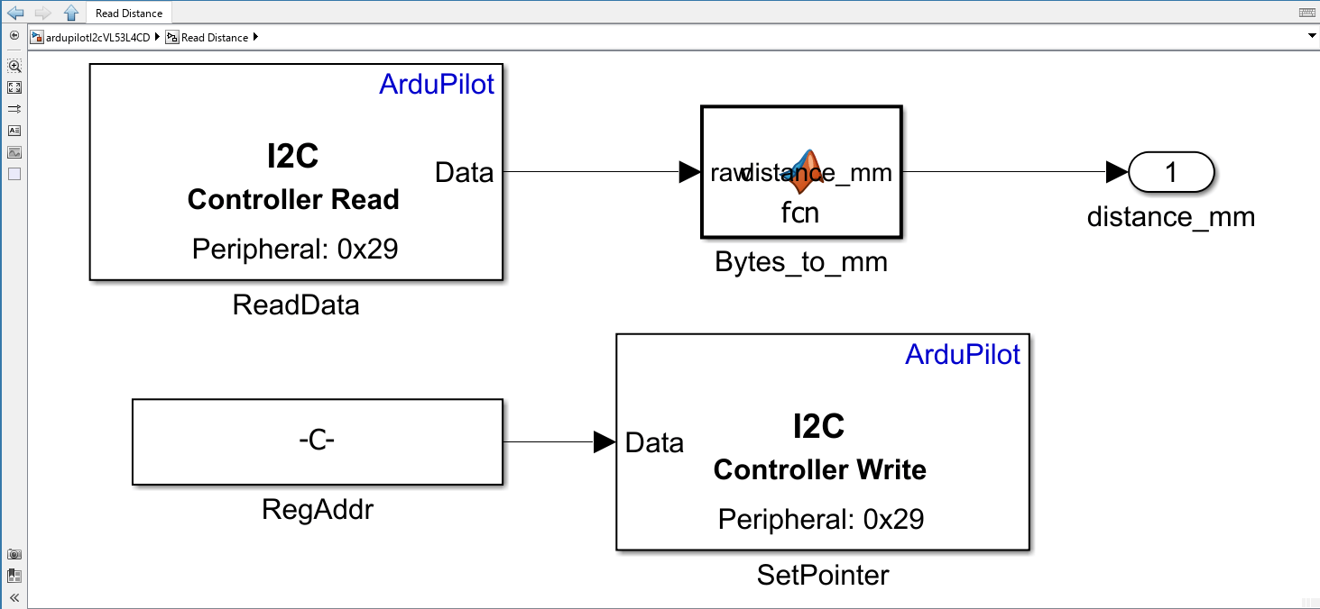
This write-then-read pattern is standard for I2C peripherals that use addressed registers. The model first selects which register to access, then reads the data from that register.
Read Range Status Subsystem
The Read Range Status subsystem reads and decodes the sensor measurement status:
SetPointer — An I2C Controller Write block writes the status register address.
CmdData — An I2C Controller Write block writes a command to prepare the status data.
ReadData — An I2C Controller Read block reads the status bytes.
Decode_Status — A MATLAB Function block decodes the raw byte into a status code.
The subsystem outputs the decoded value as status. The status codes indicate measurement validity:
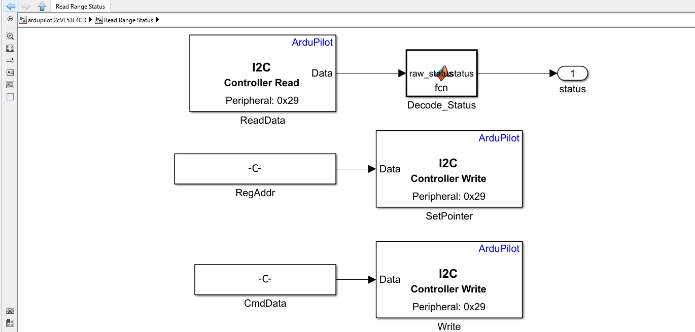
The subsystem outputs a status value that indicates the result of the distance measurement:
0— Valid: Measurement is within the sensor operating range.1— Too Close: Target is closer than the minimum range.2— Signal Fail: Insufficient signal return from the target.-1— Other: Unrecognized or unexpected status condition.
A valid distance measurement corresponds to a status value of 0. If the status is non-zero, the distance value may be unreliable.
Model Parameters
The model uses the VL53L4CD_params.m script to define constants required for I2C communication. This script runs automatically from the model InitFcn callback when the model opens or executes.
The script defines:
I2C bus configuration — The I2C bus number and the VL53L4CD peripheral address (
0x29).I2C write commands — Command payloads for reset enter, reset exit, ranging start, interrupt clear, and measurement timing configuration.
Register addresses — The sensor register addresses for reading distance data and range status.
Measurement timing parameters — The inter-measurement period and oscillator frequency used to compute the timing register value.
Default sensor configuration — The configuration payload written during sensor initialization.
The script encodes register addresses directly into the I2C write payloads because the VL53L4CD uses 16-bit register addresses, while the I2C Controller blocks transmit data as byte arrays. Each write payload therefore begins with the two-byte register address followed by the data bytes.
Configure the Model
Open the
ArduPilotVL53L4CDRead.slxmodel. This model is pre-configured to run onArduPilot Generic Board.
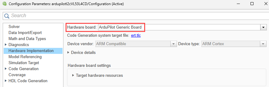
2. In the Simulink model, go to Modeling > Model Settings.
3. In the Configuration Parameters dialog box, navigate to Hardware Implementation > Hardware board and verify that ArduPilot Generic Board is selected.
4. Save the model after any hardware-specific updates.
Run the Model and Observe Results
After you complete the hardware and model configuration:
On the Hardware tab, in the in the Mode section, click Run on board and then select Run on board (External mode). If you see Connected IO selected instead of Run on board, click on it and choose Run on board (External mode)
.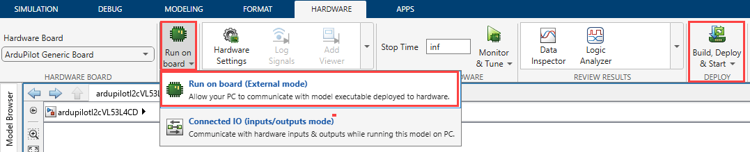
2. Click Build, Deploy & Start. After deployment, the algorithm runs autonomously on the hardware.
3. Observe the outputs:
Distance (mm) — Measured range value from the sensor
Range Status — Decoded sensor status
A valid measurement typically corresponds to a status value of 0 in this model.
When the model runs successfully:
The
Distance (mm)output displays the measured target distance.The
Range Statusoutput indicates the measurement condition.
If no target is present within range or the signal return is too weak, the status value changes to 2 (Signal Fail). If the target is closer than the minimum measurement distance, the status changes to 1 (Too Close).
Other Things to Try
Change the sensor polling rate by updating the measurement timing configuration.
Log the measured distance and status signals for analysis.
Replace the top-level display blocks with signal logging or telemetry outputs.
Add error handling for persistent invalid status values.

