CCSDS LDPC Encoder
Libraries:
Wireless HDL Toolbox /
Error Detection and Correction
Description
The CCSDS LDPC Encoder block encodes data with low-density parity-check
(LDPC) code specified in the Consultative Committee for Space Data Systems (CCSDS) Telemetry
standard. The block accepts data bits and a stream of control signals as inputs. The block
outputs encoded bits, a stream of control signals, and a signal that indicates when the block
is ready to accept new inputs. The block supports the configuration types,
(8160,7136) LDPC, and AR4JA
LDPC.
The block supports scalar input and vector inputs of size 8. The block provides an architecture suitable for HDL code generation and hardware deployment. You can use this block in a CCSDS transmitter for satellite communication for deep space missions and also for any application that requires exceptional forward error correction performance. To know more about CCSDS Telemetry standard, see [1].
Examples
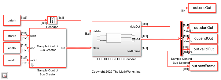
Encode Data with LDPC Code in CCSDS Telemetry Standard
Use CCSDS LDPC Encoder block to encode data bits with LDPC code.
Ports
Input
Output
Parameters
Algorithms
The CCSDS LDPC Encoder block supports the following configuration types:
(8160,7136) LDPC, and AR4JA
LDPC.
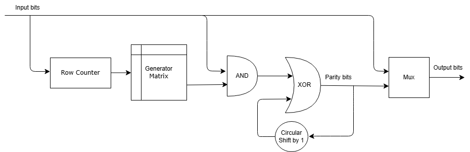
(8160, 7136) LDPC
This figure shows the block architecture for the configuration type
(8160,7136) LDPC.
For each batch of 511 input bits, the row counter increases by one. Using the current row count, the Generator Matrix look-up table (LUT) provides the corresponding row of the matrix. The algorithm XORs each input bit with the parity bits, which are circularly shifted by one position. This operation is repeated for the entire set of input bits.
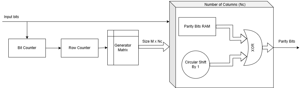
AR4JA
      LDPC
This figure shows the block architecture for the configuration type AR4JA
LDPC.
For each group of M input bits, the row counter increments by one, prompting Generator Matrix LUT block to output the corresponding row of the matrix, which consists of M rows and Nc columns. The algorithm computes parity bits using Nc parallel processing units. In each unit, depending on the value of the input bit, M parity bits are XORed with the corresponding M elements from the generator matrix. Here M is the submatrix size. The algorithm repeats this process for all inputs, circularly shifting the generator matrix by one position after each input bit is processed. Upon completion of the input bit processing, Parity Bits RAM provides the final parity bits as output.
This section provides information about the latency of the block for each of the selected configuration types.
When you set the Configuration type parameter to
(8160,7136) LDPC, the latency of the block varies based on
the type of input. Because the latency varies, use the nextFrame
control signal output port to determine when the block is ready for a new input frame.
This figure shows a sample output and latency of the block for a scalar input. The latency of the block is 5 clock cycles.

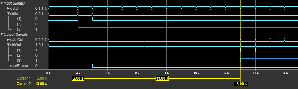
This figure shows a sample output and latency of the block for an eight-element column vector input. The latency of the block is 11 clock cycles.
When you set the Configuration type parameter to
AR4JA LDPC, the latency of the block varies based on the
block length, code rate, and input source type. Because the latency varies, use the
nextFrame control signal output port to determine when the block is
ready for a new input frame.
The following table lists the latency values of the block for different code rates and
block lengths, when specified through Property.
| Block Length | Code Rate | Latency |
|---|---|---|
| 1024 | 1/2 | 10 |
| 4096 | 10 | |
| 16384 | 49168 | |
| 1024 | 2/3 | 10 |
| 4096 | 10 | |
| 16384 | 16400 | |
| 1024 | 4/5 | 10 |
| 4096 | 10 | |
| 16384 | 10 |
The following table lists the latency values of the block for different code rates and
block lengths, when specified through Input port.
| Block Length | Code Rate | Latency |
|---|---|---|
| 1024 | 1/2 | 16 |
| 4096 | 16 | |
| 16384 | 49168 | |
| 1024 | 2/3 | 16 |
| 4096 | 16 | |
| 16384 | 16400 | |
| 1024 | 4/5 | 16 |
| 4096 | 16 | |
| 16384 | 16 |
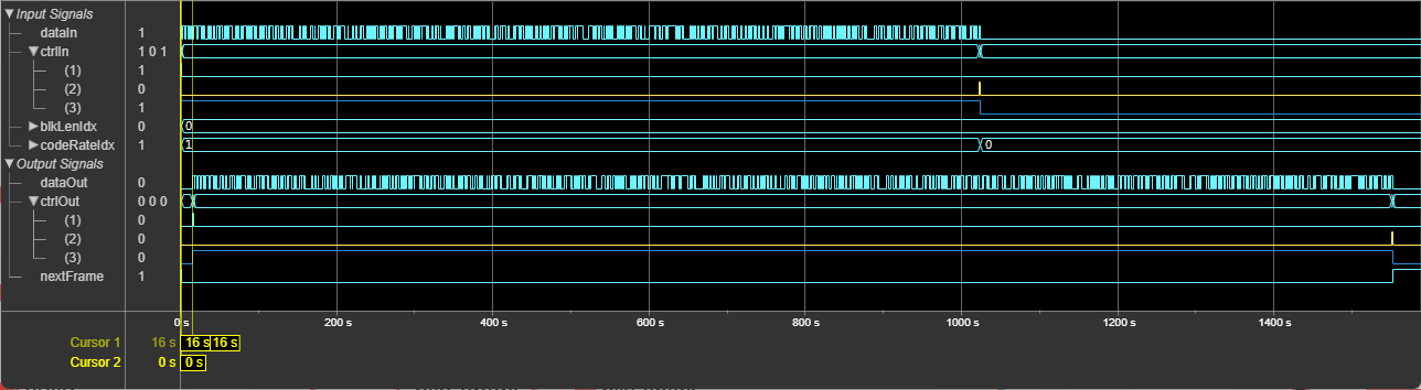
This figure shows a sample output and latency of the block when you set the
Configuration type parameter to AR4JA
LDPC with the default configuration. When you specify
blkLenIdx input port value as 0 and the
codeRateIdx input port value as 0, the latency
of the block is 16 clock cycles.
References
[1] TM Synchronization and Channel Coding. Recommendation for Space Data System Standards. CCSDS 131.0-B-3. Blue Book. Issue 3. Washington, D.C.: CCSDS, September 2017.
[2] TM Synchronization and Channel Coding. Summary of Concept and Rationale CCSDS 130.1-G-3. Green Book. Issue 3, June 2020.