Parallel Concatenation Using APP Decoder
This example shows how to decode parallel concatenated convolution codes using the APP Decoder block. This example contains a Simulink® model that contains the basic structure of a turbo decoder with a rate of 1/3, constructed using two APP Decoder blocks.
Introduction
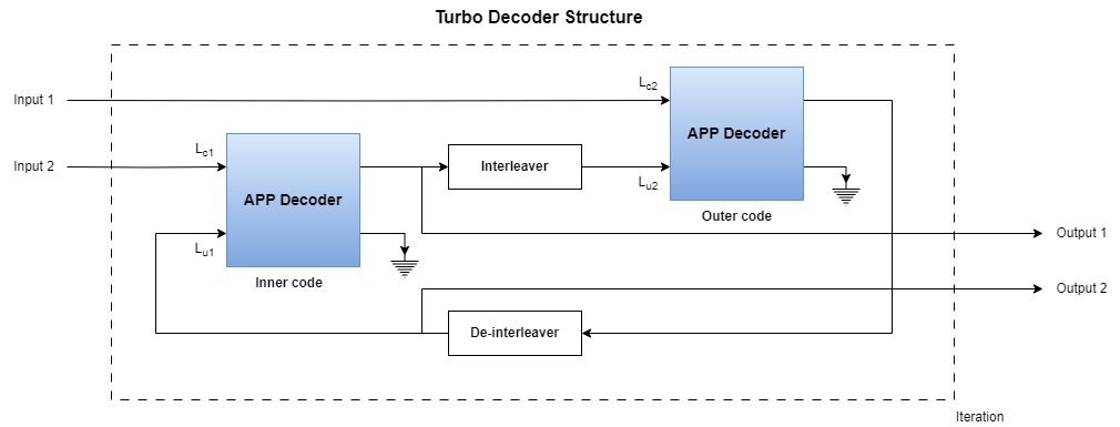
The invention of turbo codes [ 1 ], along with the development of iterative decoding principles with near Shannon limit performance, has led to their integration in a wide variety of applications. Some of the applications include deep space communications, third generation wireless standards, and digital video broadcasting [ 2 ]. You can achieve iterative decoding by using two APP Decoder blocks and by having the encoders send the output soft information to each other forming a feedback loop. The block diagram shows the conceptual design of a turbo decoder for one iteration.
Model Architecture
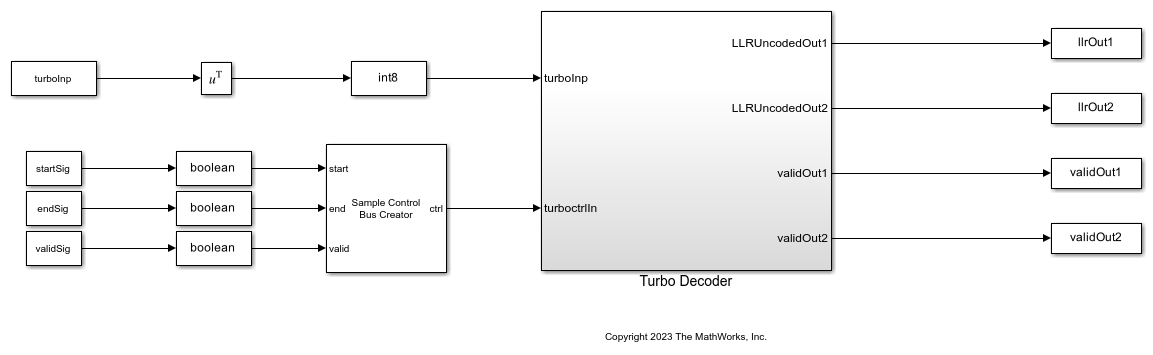
This figure shows the top level model architecture of a turbo decoder. The model accepts three samples at a time with the corresponding start, end, and valid control signals.
modelName = 'HDLParallelConcatenation';
open_system(modelName);
Turbo Decoder
The following figure shows how the APP Decoder blocks are connected in parallel to build a turbo decoder. The output from the first decoder is interleaved and provided as an input to the second decoder and the output from the second decoder is de-interleaved and provided as an input to the first decoder forming a feedback loop. The Interleaver and Deinterleaver blocks are implemented based on the HDL Interleaver and Deinterleaver example. The Store Frame and Generate Inputs subsystem stores the frame and provides input to both the decoders based on the number of iterations. The stopTime value is adjusted so that the model runs for the specified number of frames, number of iterations, and frame length.
load_system(modelName);
open_system([modelName '/Turbo Decoder']);

Set Input Variables
Create a trellis and specify the input parameters as shown in the following code. You can change the variable values in this section based on your requirements.
codeGen = [13 15]; % Specify code generator as a row vector of octal values.
feedbackConn = 13; % Specify feedback connection as a scalar and an octal value.
algorithm = 'Max'; % Specify the algorithm as 'Max' or 'Max*'.
winLen = 64;
numFrames = 10;
frameLength = 1000;
numIterations = 6;
rowforInterleave = 4;
snrRange = 0:6;
orderOfQAM = 16; % Specify the QAM modulation order as 4, 16, 64, or 256

% Configured variables with the specified input parameters. These variables
% are read-only.
codeRate = length(codeGen);
DecCodeGen = oct2dec(codeGen);
K = length(dec2bin(DecCodeGen));
trellisStructure = poly2trellis(K,codeGen,feedbackConn);
numOutputs = log2(trellisStructure.numOutputSymbols);
numTailBits = 2*numOutputs*(K-1);
if (numTailBits/3)-floor((numTailBits/3))==0
    numTailMul3 = numTailBits/3;
else
    numTailMul3 = ceil(numTailBits/3);
end
datasize = frameLength + numTailMul3;
numberOfBits = numFrames*frameLength;
latency = 2*(winLen) + 3 + 2+(2^(K-1) - 1);
reShapedIndices = reshape(1:frameLength,[],rowforInterleave)';
interlvrIndices = reshape(reShapedIndices,1,frameLength);
turboenc = comm.TurboEncoder(trellisStructure,interlvrIndices);
stpTimeForOneIter = (2 + latency + datasize) + (datasize + 12) + (datasize + latency +12);
frameGap = (2*(datasize+latency+12+1)+1)*(numIterations);
inp2enc = zeros(frameLength,numFrames);
turboDec  = comm.TurboDecoder('TrellisStructure', trellisStructure, 'InterleaverIndices', interlvrIndices, ...
    'NumIterations', numIterations,'Algorithm',algorithm);
if strcmp(algorithm,'Max')
    algo = 'Max Log MAP (max)';
else
    algo = 'Log MAP (max*)'; %#ok<UNRCH>
end
stopTime = stpTimeForOneIter*(numIterations+1)*(numFrames);
load_system(modelName);
set_param([modelName '/Turbo Decoder/APP Decoder 1'],'TermMode','Terminated');
set_param([modelName '/Turbo Decoder/APP Decoder 2'],'TermMode','Terminated');
set_param([modelName '/Turbo Decoder/APP Decoder 1'],'Algorithm',algo);
set_param([modelName '/Turbo Decoder/APP Decoder 2'],'Algorithm',algo);
Generate Input Data and Simulate Reference Function Using MATLAB
Generate the input data and simulate the reference function in MATLAB using the following steps:
Generate random binary data.
Encode the data using the
turboencfunction.Modulate the data using the
qammodfunction.Pass the modulated signal through an AWGN channel.
Demodulate the received signal using
qamdemodto give out approximated LLR values.Use the
comm.TurboDecoderobject to decode the LLR values and compute the bit error rate.
rng("default");
for snrIdx=1:length(snrRange)
simulink_input=[];
for fr=1:numFrames
    % Create random binary inputs
    inp2enc(:,fr) = randn(frameLength,1)>1;
    % Encode data using turbo encoder
    encdata = turboenc(inp2enc(:,fr));
    % Modulate data
    modulatedData = qammod(double(encdata), orderOfQAM, 'InputType', 'bit', 'UnitAveragePower', true);
    % Add noise
    snrdB = snrRange(snrIdx);
    noiseVar = 10^-(snrdB/10);
    rxSig = awgn(modulatedData,snrdB,'measured');
    % Demodulate data
    demod(:,fr) = -qamdemod(rxSig, orderOfQAM, 'OutputType', 'approxllr', 'UnitAveragePower', true,'NoiseVariance',noiseVar); %#ok<*SAGROW>
    % Decode data using turbo decoder function
    decodedBits(:,fr) = turboDec(demod(:,fr));
end
matlab_output=decodedBits(:);
matlab_output=matlab_output';% convert to a row vector
% Reshape input to row vector
matlab_input = reshape(inp2enc,[],numberOfBits);
% Calculate bit error rate (BER)
BER_matlab(1,snrIdx) = sum(xor(matlab_output,matlab_input))/numberOfBits;
Run Model
Reshape the qamdemod function output and provide it as input to the HDLParallelConcatenation model. Generate the start, valid, and end signals based on the number of iterations and the latency of the APP Decoder block. Run the model and capture the bit error rate from the output signals LLRUncodedOut1 and LLRUncodedOut2.
inp2Sim = [];
startSig = [];
endSig = [];
validSig = [];
demodTerm = zeros(3*datasize,numFrames);
demodTerm(1:size(demod,1),1:size(demod,2)) = demod;
for fr =1:numFrames % Generate input signals to Simulink
    inp2Sim = [inp2Sim;demodTerm(1:3*datasize,fr);zeros(3*frameGap,1)]; %#ok<*AGROW>
    startSig = [startSig;true; false(datasize-1,1);false(frameGap,1)]; % Start signal
    endSig = [endSig;false(datasize-1,1); true;false(frameGap,1)]; % End signal
    validSig = [validSig;true(datasize,1);false(frameGap,1)];  % Valid signal
end
turboInp = reshape(inp2Sim,3,[]).';
% Run Simulink model
sim(modelName);
% Collect outputs from Simulink
totaluncodedoutput1 = llrOut1(validOut1);
totaluncodedoutput2 = llrOut2(validOut2);
LLRu_out_sim = totaluncodedoutput1+totaluncodedoutput2;
simulink_output = LLRu_out_sim>=0;
% Calculate bit error rate
BER_simulink(1,snrIdx) = sum(xor(simulink_output.',matlab_input))/numberOfBits;
end
Verify and Plot Results
Collect the bit error rate from MATLAB reference and Simulink model outputs and plot the results to show the signal-to-noise ratio (SNR) versus bit error rate (BER) performance.
semilogy(snrRange,BER_matlab,'--o');
hold on
semilogy(snrRange,BER_simulink,'-s');
grid on
legend('MATLAB output','Simulink output');
xlabel("Signal-to-Noise Ratio (in dB)");
ylabel("Bit Error Rate (BER)");
title("Turbo decoding of 16 QAM with floating- and fixed-point data");

Generate HDL Code
To check and generate HDL for this example, you must have an HDL Coder™ license. Use the makehdl and makehdltb commands to generate the HDL code and test bench for the Turbo Decoder subsystem.
Synthesize the Turbo Decoder subsystem on a Xilinx® Zynq®-7000 ZC706 evaluation board. The frequency obtained after place and route is about 235 MHz. The following table shows the post place and route resource utilization results for an 8-bit LLR input.
F = table(...
    categorical({'Slice LUT';'Slice Registers';'BRAM';'DSP';}) ,...
    categorical({'5551';'4396';'7.5';'2'}), ...
    'VariableNames',{'Resources','Usage'});

disp(F);
       Resources       Usage
    _______________    _____

    Slice LUT          5551
    Slice Registers    4396
    BRAM               7.5
    DSP                2
References
Berrou, C., and A. Glavieux. "Near Optimum Error Correcting Coding and Decoding: Turbo-Codes." IEEE Transactions on Communications 44, no. 10 (October 1996) : 1261-71. https://doi.org/10.1109/26.539767.
Schlegel, Christian, and Lance Perez. Trellis and Turbo Coding. IEEE Press Series on Digital & Mobile Communication. Hoboken, NJ: IEEE Press, 2004.