Main Content

wlanLLTFChannelEstimate

Channel estimation using L-LTF

Description

example

chEst = wlanLLTFChannelEstimate(demodSig,cfg) returns the channel estimate between the transmitter and all receive antennas using the demodulated L-LTF1 , demodSig, given the parameters specified in configuration object cfg.

example

chEst = wlanLLTFChannelEstimate(demodSig,cbw) returns the channel estimate given channel bandwidth cbw. The channel bandwidth can be used instead of the configuration object.

example

chEst = wlanLLTFChannelEstimate(___,span) returns the channel estimate and performs frequency smoothing over the specified filter span. For more information, see Frequency Smoothing.

This syntax supports input options from prior syntaxes.

Examples

collapse all

Create VHT format configuration object. Generate a time-domain waveform for an 802.11ac VHT packet.

vht = wlanVHTConfig;
txWaveform = wlanWaveformGenerator([1;0;0;1],vht);

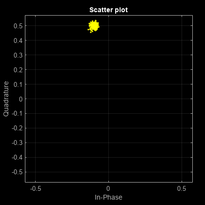
Multiply the transmitted VHT signal by -0.1 + 0.5i and pass it through an AWGN channel with a 30 dB signal-to-noise ratio.

rxWaveform = awgn(txWaveform*(-0.1+0.5i),30);

Extract the L-LTF field indices and demodulate the L-LTF. Perform channel estimation without frequency smoothing.

idxLLTF = wlanFieldIndices(vht,'L-LTF');
demodSig = wlanLLTFDemodulate(rxWaveform(idxLLTF(1):idxLLTF(2),:),vht);

est = wlanLLTFChannelEstimate(demodSig,vht);

Plot the channel estimate.

scatterplot(est)
grid

The channel estimate matches the complex channel multiplier.

Generate a time domain waveform for an 802.11n HT packet, pass it through a TGn fading channel and perform L-LTF channel estimation. Trailing zeros are added to the waveform to allow for TGn channel delay.

Create the HT packet configuration and transmit waveform.

cfgHT = wlanHTConfig;
txWaveform = wlanWaveformGenerator([1;0;0;1],cfgHT);

Configure a TGn channel with 20 MHz bandwidth.

tgnChannel = wlanTGnChannel;
tgnChannel.SampleRate = 20e6;

Pass the waveform through the TGn channel, adding trailing zeros to allow for channel delay.

rxWaveform = tgnChannel([txWaveform; zeros(15,1)]);

Skip the first four samples to synchronize the received waveform for channel delay.

rxWaveform = rxWaveform(5:end,:);

Extract the L-LTF and perform channel estimation.

idnLLTF = wlanFieldIndices(cfgHT,'L-LTF');
sym = wlanLLTFDemodulate(rxWaveform(idnLLTF(1):idnLLTF(2),:),cfgHT);
est = wlanLLTFChannelEstimate(sym,cfgHT);

Create a VHT format configuration object. Using these objects, generate a time-domain waveform for an 802.11ac VHT packet.

vht = wlanVHTConfig('ChannelBandwidth','CBW80');
txWaveform = wlanWaveformGenerator([1;0;0;1],vht);

Multiply the transmitted VHT signal by -0.4 + 0.3i and pass it through an AWGN channel.

rxWaveform = awgn(txWaveform*(-0.4+0.3i),30);

Specify the channel bandwidth for demodulation and channel estimation. Extract the L-LTF field indices, demodulate the L-LTF, and perform channel estimation without frequency smoothing.

chanBW = 'CBW80';
idxLLTF = wlanFieldIndices(vht,'L-LTF');
demodSig = wlanLLTFDemodulate(rxWaveform(idxLLTF(1):idxLLTF(2),:),chanBW); 
est = wlanLLTFChannelEstimate(demodSig,chanBW);

Plot the channel estimate.

scatterplot(est)
grid

The channel estimate matches the complex channel multiplier.

Create a VHT format configuration object. Generate a time-domain waveform for an 802.11ac VHT packet.

vht = wlanVHTConfig;
txWaveform = wlanWaveformGenerator([1;0;0;1],vht);

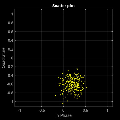
Multiply the transmitted VHT signal by 0.2 - 0.6i and pass it through an AWGN channel having a 10 dB SNR.

rxWaveform = awgn(txWaveform*complex(0.2,-0.6),10);

Extract the L-LTF from the received waveform. Demodulate the L-LTF.

idxLLTF = wlanFieldIndices(vht, 'L-LTF');
lltfDemodSig = wlanLLTFDemodulate(rxWaveform(idxLLTF(1):idxLLTF(2),:),vht);

Use the demodulated L-LTF signal to generate the channel estimate.

est = wlanLLTFChannelEstimate(lltfDemodSig,vht);

Plot the channel estimate.

scatterplot(est)
grid

The channel estimate is noisy, which may lead to inaccurate data recovery.

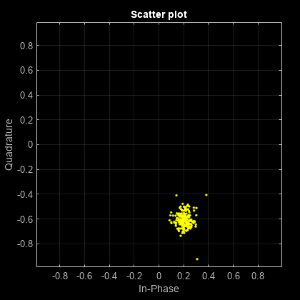
Estimate the channel again with the filter span set to 11.

est = wlanLLTFChannelEstimate(lltfDemodSig,vht,11);
scatterplot(est)
grid

The filtering provides a better channel estimate.

Create a VHT format configuration object. Generate L-LTF and VHT-SIG-A fields.

vht = wlanVHTConfig;
txLLTF = wlanLLTF(vht);
txSig = wlanVHTSIGA(vht);

Create a TGac channel for an 80 MHz bandwidth and a Model-A delay profile. Pass the transmitted L-LTF and VHT-SIG-A signals through the channel.

tgacChan = wlanTGacChannel('SampleRate',80e6,'ChannelBandwidth','CBW80', ...
    'DelayProfile','Model-A');

rxLLTFNoNoise = tgacChan(txLLTF);
rxSigNoNoise = tgacChan(txSig);

Create an AWGN noise channel with an SNR = 15 dB. Add the AWGN noise to L-LTF and VHT-SIG-A signals.

chNoise = comm.AWGNChannel('NoiseMethod','Signal to noise ratio (SNR)', ...
    'SNR',15);

rxLLTF = chNoise(rxLLTFNoNoise);
rxSig = chNoise(rxSigNoNoise);

Create an AWGN channel having a noise variance corresponding to a 9 dB noise figure receiver. Pass the faded signals through the AWGN channel.

nVar = 10^((-228.6 + 10*log10(290) + 10*log10(80e6) + 9)/10);
awgnChan = comm.AWGNChannel('NoiseMethod','Variance','Variance',nVar);

rxLLTF = awgnChan(rxLLTF);
rxSig = awgnChan(rxSig);

Demodulate the received L-LTF.

demodLLTF = wlanLLTFDemodulate(rxLLTF,vht);

Estimate the channel using the demodulated L-LTF.

chEst = wlanLLTFChannelEstimate(demodLLTF,vht);

Recover the VHT-SIG-A signal and verify that there was no CRC failure.

[recBits,crcFail] = wlanVHTSIGARecover(rxSig,chEst,nVar,'CBW80');
crcFail
crcFail = logical
   0

Input Arguments

collapse all

Demodulated L-LTF OFDM symbols, specified as an NST-by-NSYM-by-NR array. NST is the number of occupied subcarriers. NSYM is the number of demodulated L-LTF symbols (one or two). NR is the number of receive antennas. Each column of the 3-D array is a demodulated L-LTF OFDM symbol. If you specify two L-LTF symbols, wlanLLTFChannelEstimate averages the channel estimate over both symbols.

Data Types: single | double
Complex Number Support: Yes

Format configuration, specified as one of these objects:

The wlanLLTFChannelEstimate function uses the ChannelBandwidth property of cfg.

Channel bandwidth, specified as one of these values.

  • 'CBW5' — Channel bandwidth of 5 MHz

  • 'CBW10' — Channel bandwidth of 10 MHz

  • 'CBW20' — Channel bandwidth of 20 MHz

  • 'CBW40' — Channel bandwidth of 40 MHz

  • 'CBW80' — Channel bandwidth of 80 MHz

  • 'CBW160' — Channel bandwidth of 160 MHz

  • 'CBW320' — Channel bandwidth of 320 MHz

Data Types: char | string

Filter span of the frequency smoothing filter, specified as a positive odd integer and expressed as a number of subcarriers. Frequency smoothing is applied only when span is specified and is greater than one. See Frequency Smoothing.

Data Types: single | double

Output Arguments

collapse all

Channel estimate containing data and pilot subcarriers, returned as an NST-by-1-by-NR array. NST is the number of occupied subcarriers. The value of 1 corresponds to the single transmitted stream in the L-LTF. NR is the number of receive antennas.

More About

collapse all

L-LTF

The L-LTF is the second field in the 802.11™ OFDM PLCP legacy preamble. The L-LTF is a component of EHT, HE, VHT, HT, and non-HT PPDUs.

The L-LTF, second in the legacy preamble

Channel estimation, fine frequency offset estimation, and fine symbol timing offset estimation rely on the L-LTF.

The L-LTF is composed of a cyclic prefix (CP) followed by two identical long training symbols (C1 and C2). The CP consists of the second half of the long training symbol.

The cyclic prefix followed by the two long training symbols in the L-LTF

The L-LTF duration varies with channel bandwidth.

Channel Bandwidth (MHz)Subcarrier Frequency Spacing ΔF (kHz)Fast Fourier Transform (FFT) Period (TFFT = 1 / ΔF)Cyclic Prefix or Training Symbol Guard Interval (GI2) Duration (TGI2 = TFFT / 2)L-LTF Duration (TLONG = TGI2 + 2 × TFFT)
20, 40, 80, 160, and 320312.53.2 μs1.6 μs8 μs
10156.256.4 μs3.2 μs16 μs
578.12512.8 μs6.4 μs32 μs

Frequency Smoothing

Frequency smoothing can improve channel estimation by averaging out noise.

Frequency smoothing is recommended only for cases in which a single transmit antenna is used. Frequency smoothing consists of applying a moving-average filter that spans multiple adjacent subcarriers. Channel conditions dictate whether frequency smoothing is beneficial.

  • If adjacent subcarriers are highly correlated, frequency smoothing results in significant noise reduction.

  • In a highly frequency-selective channel, smoothing can degrade the quality of the channel estimate.

References

[1] Van de Beek, J.-J., O. Edfors, M. Sandell, S. K. Wilson, and P. O. Borjesson. “On Channel Estimation in OFDM Systems.” Vehicular Technology Conference, IEEE 45th, Volume 2, IEEE, 1995.

[2] IEEE Std 802.11-2020 (Revision of IEEE Std 802.11-2016). “Part 11: Wireless LAN Medium Access Control (MAC) and Physical Layer (PHY) Specifications.” IEEE Standard for Information Technology — Telecommunications and Information Exchange between Systems — Local and Metropolitan Area Networks — Specific Requirements.

Extended Capabilities

Version History

Introduced in R2015b

expand all


1 IEEE® Std 802.11-2012 Adapted and reprinted with permission from IEEE. Copyright IEEE 2012. All rights reserved.