Include MATLAB Functions in HDL Test Bench
This example shows how to include MATLAB® functions as components of an HDL test bench. By utilizing MATLAB functions that represent the system-level behaviors, you can reduce the time required to verify RTL design. This example includes two MATLAB functions: one for generating stimuli and the other for creating a predictor model within a top-level HDL test bench. You run the test bench and observe the results within HDL simulator.
This example takes the perspective of an HDL verification engineer developing a test bench for verifying the RTL using an HDL simulator. It emphasizes the usage of the command line for development and running within the HDL simulator environment, including the ability to call MATLAB directly from within that environment. For the step-by-step process of integrating MATLAB function into your HDL test bench, see Verify HDL Module with MATLAB Test Bench.
Design Tasks
To verify the functionality of an RTL design under test (DUT), you need to develop a test bench. The test bench includes a stimulus component that supplies test inputs and a predictor component that provides expected DUT outputs. You run the test bench in an HDL simulator, comparing the DUT output with the predictor's output at each clock cycle for numerical accuracy. You must connect the stimulus, predictor, and build a top-level test bench as shown below:

To comprehensively test the RTL with a variety of test cases, you require a stimulus component capable of providing different sets of test data based on parameters. The predictor component must contain the behavioral model of the DUT to provide the expected value for any stimulus. Modeling these components in HDL languages can be challenging. However, using MATLAB functions saves time during RTL verification and helps in detecting issues earlier.
Test Bench Structure
This example uses a low-pass filter in Verilog® as the DUT and two MATLAB functions for the stimulus and the predictor. The example uses these files.
DUT— Verilog file to define a low-pass filter, the design under teststimulus— Verilog file to define the port interface in HDL code for the stimulus componentstimulus_fcn— MATLAB function to define the stimulus functionpredictor— Verilog file to define the port interface in HDL code for the predictor componentpredictor_fcn— MATLAB function to define the predictor function that models the behavior of low pass filtertb_top— Top-level System Verilog test bench that instantiates components and wires them appropriatelycompilehdl_and_run_mq— TCL script file to compile the test bench and run it in an HDL simulator
To begin, you must perform a few setup tasks, such as establishing communication with the HDL simulator and launching the simulator from within MATLAB. The subsequent steps are then executed directly within the HDL simulator.
Setup in MATLAB
If you are in the MATLAB session, you can perform these steps.
1. Starting the MATLAB Server
Run the hdldaemon command for communication between the HDL simulator and MATLAB.
hdldaemon
2. Launch HDL Simulator
Launch Mentor Graphics® ModelSim® or Questa® using vsim command in MATLAB. This configures the ModelSim for use with MATLAB and Simulink®.
vsim
Alternatively, you can open MATLAB in nodesktop mode allowing you to develop in command line environment. Follow the steps below to open MATLAB and navigate to the example folder. Then, run above commands mentioned in Setup in MATLAB.
On a Windows® system, enter this command at your system command prompt.
matlab -nodesktop
On a Linux® system, enter this command at your system command prompt.
xterm -e "matlab -nodesktop " &
Run Test Bench in HDL Simulator
To verify the RTL exhaustively, you typically need a variety of directed tests to test specific functionality or cover specific RTL code. This is achieved by adding ports in the Verilog stub file and setting their values using parameters in the tb_top file. You can then set up the arguments of the MATLAB stimulus function for each test case from the HDL simulator. Add the STIM_TYPE_VAL, STIM_LENGTH, and CHIRP_FINAL_FREQ ports.
1. Set Test Case Variables
In ModelSim, set the test case variables corresponding to an impulse stimulus with a length of 50 samples. Run these commands in ModelSim.
set STIM_TYPE_VAL 0
set STIM_LEN 50
2. Compile HDL Files and Run Test Bench
To compile the HDL files, bind the MATLAB components with HDL files and run the test cases, you can write all the commands in a TCL file and run the TCL at the ModelSim.
do compilehdl_and_run_mq.tcl
The TCL script compilehdl_and_run_mq performs these operations in order:
Compiles the Verilog modules, respecting the hierarchical order.
Loads the
tb_topentity for verification and sets up ModelSim so it can establish a communication link with MATLAB. This is done byvsimmatlabcommand.
vsimmatlab -t 1ns -voptargs=+acc work.tb_top +STIM_TYPE_VAL=$STIM_TYPE_VAL +STIM_LENGTH=$STIM_LENGTH +CHIRP_FINAL_FREQ=$CHIRP_FINAL_FREQ
The values of test case variables are passed using plus args.
Binds MATLAB functions with corresponding Verilog modules.
For each MATLAB function, there is a Verilog module that defines only the input and output ports and is otherwise empty. The matlabcp function uses the empty stub Verilog component as a shell for communication between MATLAB and the HDL simulator. The MATLAB function provides functionality. For information about creating the necessary files for matlabcp, see Create a MATLAB Component Function.
To bind the Verilog stimulus component instantiation, /tb_top/u_stimulus, with the MATLAB function, stimulus_fcn, in the HDL simulator, following command is used:
matlabcp /tb_top/u_stimulus 10 ns -repeat 10 ns -mfunc stimulus_fcn.m -use_instance_obj
Similarly, the Verilog predictor component, /tb_top/u_predictor, is bound with the MATLAB function predictor_fcn using this command in ModelSim command window.
matlabcp /tb_top/u_predictor 10 ns -repeat 10 ns -mfunc predictor_fcn.m -use_instance_obj
Note that the matlabcp function is specified with the -use_instance_obj argument in the above bindings. This argument instructs the MATLAB function stimulus_fcn, specified with the -mfunc argument, to use an HDL instance object passed to the function. See Test Bench and Component Function Writing.
Sets up clocks, reset, and clk_enable stimuli for the test bench.
Runs the simulation.
Simulation Results
Running the simulation produces these waveforms. You can visualize the impulse response of the filter.

The test bench produces these logs as part of the run indicating that the outputs of the RTL match the expected value within a threshold tolerance of 8191.
![]()
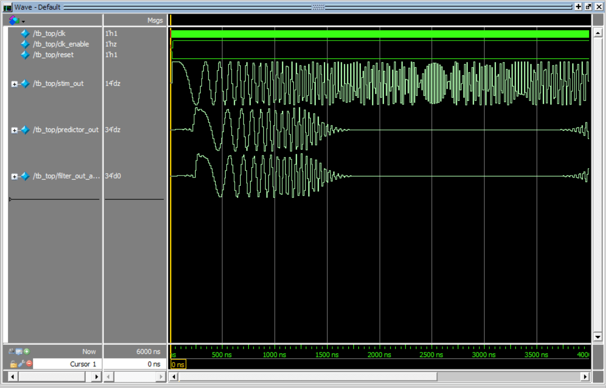
To run the test bench for a different test case, change the STIM_TYPE variable and corresponding required parameters. For example, to run the test bench from the chirp test case, follow these steps.
1. Quit the current simulation by typing this command in ModelSim.
quit -sim
2. Set the STIM_TYPE_VAL variable in the simulator.
set STIM_TYPE_VAL 1
3. Set the chirp final frequency.
set CHIRP_FINAL_FREQ 2e3
4. Set the stimulus with a length of 1024 samples.
set STIM_LEN 1024
5. Run the TCL file.
do compilehdl_and_run_mq.tcl
The simulator returns these outputs from the test bench. The amplitude of filter_out_actual for the high-frequency component is reduced by the low-pass filter you design in Verilog.
![]()
Conclusion
In this example, you develop an HDL test bench to verify the RTL of a low-pass filter. You use MATLAB components for the stimulus and predictor components of the test bench. You define test cases to test the DUT by passing arguments to the stimulus function. By incorporating MATLAB functions in an HDL test bench, you reduce the time required to create a full-featured HDL test bench by using system-level models for the low-pass filter and stimulus functions.
See Also
You can also select a web site from the following list:
Americas
- América Latina (Español)
- Canada (English)
- United States (English)
Europe
- Belgium (English)
- Denmark (English)
- Deutschland (Deutsch)
- España (Español)
- Finland (English)
- France (Français)
- Ireland (English)
- Italia (Italiano)
- Luxembourg (English)
- Netherlands (English)
- Norway (English)
- Österreich (Deutsch)
- Portugal (English)
- Sweden (English)
- Switzerland
- United Kingdom (English)