nrPhaseNoiseCompensate
R2026bDescription
dataOut = nrPhaseNoiseCompensate(carrier,dataSym,dataInd,cpe)dataSym. To compensate for the CPE, the function maps the equalized
data symbols dataSym to their resource element locations
dataInd within a resource grid defined by the carrier configuration
carrier. Then, it uses the estimated CPE cpe to
correct symbol‑wise phase distortion.
Examples
Estimate and compensate for the CPE of a physical downlink shared channel (PDSCH) transmission, in the presence of phase noise, by using equalized PT‑RS symbols.
To ensure simulation results are repeatable, initialize the random number generator with a fixed seed. For greater statistical accuracy, run the simulation multiple times with different seeds and compute the average results.
rng("default")Configure the carrier using an nrCarrierConfig object. Specify a subcarrier spacing of 60 kHz with a transmission bandwidth of 50 MHz operating in frequency range 2 (FR2).
carrier = nrCarrierConfig;
carrier.NSizeGrid = 66;
carrier.SubcarrierSpacing = 60;
Configure the PDSCH that occupies the complete carrier and enable PT-RS.
pdsch = nrPDSCHConfig(PRBSet=0:carrier.NSizeGrid-1, ...
    Modulation="64QAM", ...
    EnablePTRS=true, ...
    DMRS=nrPDSCHDMRSConfig( ...
    NumCDMGroupsWithoutData=1, ...
    NIDNSCID=1));
Enable PT‑RS for the PDSCH, and configure the PT‑RS time and frequency density. Set a time density of 1 to place a PT‑RS in every OFDM symbol within the PDSCH allocation, which enables per‑OFDM‑symbol CPE estimation.
pdsch.EnablePTRS = true;
pdsch.PTRS.TimeDensity = 1;
Generate DM-RS symbols and indices.
dmrsInd = nrPDSCHDMRSIndices(carrier,pdsch);
dmrsSym = nrPDSCHDMRS(carrier,pdsch);
Generate the PT-RS indices and symbols according to the PDSCH configuration.
ptrsInd = nrPDSCHPTRSIndices(carrier,pdsch);
ptrsSym = nrPDSCHPTRS(carrier,pdsch);
Generate coded bits and PDSCH symbols using the nrPDSCH function.
[dataInd,pdschInfo] = nrPDSCHIndices(carrier,pdsch);
codedBits = randi([0 1],pdschInfo.G,1);
pdschSym = nrPDSCH(carrier,pdsch,codedBits);
Create and populate resource grid with DM-RS, PT-RS, and PDSCH data symbols.
txGrid = nrResourceGrid(carrier,pdsch.NumLayers);
txGrid(dmrsInd) = dmrsSym;
txGrid(ptrsInd) = ptrsSym;
txGrid(dataInd) = pdschSym;
Apply OFDM modulation to the transmitted waveform using the nrOFDMModulate function.
[txWaveform,ofdmInfo] = nrOFDMModulate(carrier,txGrid);
Model oscillator phase noise using the nrPhaseNoise System object™. Set the carrier frequency to 30 GHz corresponding to FR2.
Fc = 30e9;
sr = ofdmInfo.SampleRate;

pnoise = nrPhaseNoise(CarrierFrequency=Fc, ...
    SampleRate=sr,...
    RandomStream="mt19937ar");
Apply oscillator phase noise to the modulated OFDM waveform.
rxWaveform = pnoise(txWaveform);
Demodulate the received waveform using the nrOFDMDemodulate function.
rxGrid = nrOFDMDemodulate(carrier,rxWaveform);
Estimate the channel using the nrChannelEstimate function.
[estChannelGrid,noiseEst] = nrChannelEstimate(carrier,rxGrid,dmrsInd,dmrsSym,CDMLengths=[2 1]);
Extract and equalize PT‑RS resource elements and obtain PT‑RS symbols.
[ptrsRx,ptrsHest] = nrExtractResources(ptrsInd,rxGrid,estChannelGrid);
ptrsEqualized = nrEqualizeMMSE(ptrsRx,ptrsHest,noiseEst);
Estimate the CPE per OFDM symbol using the nrPhaseNoiseEstimate function.
cpe = nrPhaseNoiseEstimate(carrier,ptrsEqualized,ptrsInd,ptrsSym);
disp(cpe)
0.0012 0.0151 0.0056 -0.0039 0.0233 0.0018 -0.0087 -0.0055 -0.0025 0.0152 0.0118 0.0053 0.0193 0.0363
Extract and equalize the PDSCH data symbols from the received grid for CPE compensation.
[dataRx,dataHest] = nrExtractResources(dataInd,rxGrid,estChannelGrid);
dataEqualized = nrEqualizeMMSE(dataRx,dataHest,noiseEst);
Calculate the error vector magnitude (EVM) for equalized symbols before CPE compensation using the nrEVM function.
evm_Before_CPE = nrEVM(pdschSym,dataEqualized)
evm_Before_CPE =
0.0426
Compensate the data symbols for CPE using the nrPhaseNoiseCompensate function.
dataOut = nrPhaseNoiseCompensate(carrier,dataRx,dataInd,cpe);
Calculate the EVM for the symbols after CPE compensation, and display the relative EVM improvement.
evm_After_CPE = nrEVM(pdschSym,dataOut)
evm_After_CPE =
0.0369
relative_EVM_Improvement = 100*(evm_Before_CPE - evm_After_CPE)/evm_Before_CPE
relative_EVM_Improvement =
13.4564
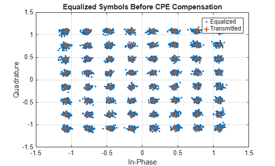
Plot the constellation before CPE compensation. The received symbols show phase rotation because of the phase noise.
figure
plot(dataEqualized,".",MarkerSize=8)
hold on
plot(pdschSym,"+",MarkerSize=10,LineWidth=1.5)
grid on
title("Equalized Symbols Before CPE Compensation")
xlabel("In-Phase")
ylabel("Quadrature")
legend("Equalized","Transmitted")
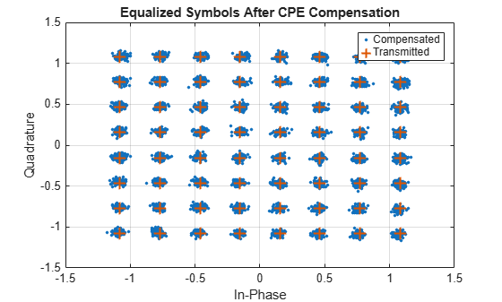
Plot constellation after CPE compensation.
figure
plot(dataOut,".",MarkerSize=8)
hold on
plot(pdschSym,"+",MarkerSize=10,LineWidth=1.5)
grid on
title("Equalized Symbols After CPE Compensation")
xlabel("In-Phase")
ylabel("Quadrature")
legend("Compensated","Transmitted")
Estimate and compensate for CPE in a DFT-s-OFDM physical uplink shared channel (PUSCH) transmission in the presence of phase noise.
To ensure simulation results are repeatable, initialize the random number generator with a fixed seed. For greater statistical accuracy, run the simulation for multiple times with different seeds and compute the average results.
rng(1)
Configure the carrier using an nrCarrierConfig object. Specify a subcarrier spacing of 60 kHz with a transmission bandwidth of 50 MHz operating in frequency range 2 (FR2).
carrier = nrCarrierConfig(NSizeGrid=66,SubcarrierSpacing=60);
Configure a transform-precoded PUSCH that occupies the complete carrier and enable PT-RS.
pusch = nrPUSCHConfig( ...
    PRBSet=0:carrier.NSizeGrid-1, ...
    SymbolAllocation=[0 carrier.SymbolsPerSlot], ...
    TransformPrecoding=true, ...
    Modulation="16QAM", ...
    EnablePTRS=true);
pusch.PTRS = nrPUSCHPTRSConfig(NumPTRSSamples=4,NumPTRSGroups=8);
Generate the PUSCH resource element indices and PT-RS reference indices, and generate the DM-RS and PT-RS reference symbols.
[puschInd,puschInfo,ptrsRefInd] = nrPUSCHIndices(carrier,pusch);
dmrsInd = nrPUSCHDMRSIndices(carrier,pusch);
dmrsSym = nrPUSCHDMRS(carrier,pusch);
ptrsRefSym = nrPUSCHPTRS(carrier,pusch);
Generate the coded bits and PUSCH symbols using the nrPUSCH function. When transform precoding is enabled, nrPUSCH multiplexes the data and PT-RS symbols before transform precoding to form the PUSCH symbol sequence.
cw = randi([0 1],puschInfo.G,1);
puschSym = nrPUSCH(carrier,pusch,cw);
Create and populate the resource grid with PUSCH and DM-RS symbols. When transform precoding is enabled, the PUSCH symbols include PT-RS information in addition to data symbols.
txGrid = nrResourceGrid(carrier);
txGrid(puschInd) = puschSym;
txGrid(dmrsInd) = dmrsSym;
Perform OFDM modulation on the transmitted waveform.
[txWaveform,ofdmInfo] = nrOFDMModulate(carrier,txGrid);
Model oscillator phase noise using the nrPhaseNoise System object™.
pnoise = nrPhaseNoise( ...
    CarrierFrequency=30e9, ...
    SampleRate=ofdmInfo.SampleRate, ...
    RandomStream="mt19937ar");
Apply oscillator phase noise to the transmit waveform and demodulate the received waveform.
rxGrid = nrOFDMDemodulate(carrier,pnoise(txWaveform));
Estimate the channel using the nrChannelEstimate function.
[estChannelGrid,noiseEst] = nrChannelEstimate(carrier,rxGrid,dmrsInd,dmrsSym,CDMLengths=pusch.DMRS.CDMLengths);
Extract and equalize the received PUSCH resource elements.
[puschRx,puschHest] = nrExtractResources(puschInd,rxGrid,estChannelGrid);
puschEq = nrEqualizeMMSE(puschRx,puschHest,noiseEst);
Perform transform de-precoding on the equalized PUSCH symbols and extract the PT-RS symbols.
numPRB = numel(puschInfo.PRBSet);
puschEqDeprecode = nrTransformDeprecode(puschEq,numPRB);
ptrsIndInPUSCH = nrPUSCHPTRSIndices(carrier,pusch);
ptrsEq = puschEqDeprecode(ptrsIndInPUSCH);
Estimate the CPE per OFDM symbol using the nrPhaseNoiseEstimate function.
cpe = nrPhaseNoiseEstimate(carrier,ptrsEq,ptrsRefInd,ptrsRefSym)
cpe = 1×14

    0.0047    0.0152    0.0043   -0.0066    0.0222    0.0003   -0.0285   -0.0128   -0.0100    0.0133    0.0246    0.0119    0.0246    0.0353
Compensate the data symbols using the nrPhaseNoiseCompensate function.
dataOut = nrPhaseNoiseCompensate(carrier,puschEq,puschInd,cpe);
Perform transform de-precoding on the compensated and reference PUSCH symbols. Then, remove the PT-RS locations from the equalized, compensated, and reference PUSCH symbols and use the remaining data symbols for EVM measurement.
puschEqCompDeprecode = nrTransformDeprecode(dataOut,numPRB);
puschRefDeprecode = nrTransformDeprecode(puschSym,numPRB);

dataEq = puschEqDeprecode;
dataEq(ptrsIndInPUSCH) = [];

dataComp = puschEqCompDeprecode;
dataComp(ptrsIndInPUSCH) = [];

dataRef = puschRefDeprecode;
dataRef(ptrsIndInPUSCH) = [];
Calculate the EVM for symbols after CPE compensation and display the relative EVM improvement.
evm_Before_CPE = nrEVM(dataEq,dataRef)
evm_Before_CPE =
0.0422
evm_After_CPE = nrEVM(dataComp,dataRef)
evm_After_CPE =
0.0390
relative_EVM_Improvement = 100*(evm_Before_CPE-evm_After_CPE)/evm_Before_CPE
relative_EVM_Improvement =
7.6200
Input Arguments
Output Arguments
Extended Capabilities
Version History
Introduced in R2026b

