nrPhaseNoiseEstimate
R2026bDescription
cpe = nrPhaseNoiseEstimate(carrier,eqSym,refInd,refSym)cpe from
equalized symbols. To estimate CPE, the function compares the equalized phase tracking
reference signal (PT-RS) symbols eqSym to the known PT-RS symbols
refSym at the specified resource element locations
refInd within a resource grid defined by the carrier parameters
carrier.
For more information about how the function computes CPE from the equalized PT-RS symbols, see Algorithms.
Examples
Estimate and compensate for the CPE of a physical downlink shared channel (PDSCH) transmission, in the presence of phase noise, by using equalized PT‑RS symbols.
To ensure simulation results are repeatable, initialize the random number generator with a fixed seed. For greater statistical accuracy, run the simulation multiple times with different seeds and compute the average results.
rng("default")Configure the carrier using an nrCarrierConfig object. Specify a subcarrier spacing of 60 kHz with a transmission bandwidth of 50 MHz operating in frequency range 2 (FR2).
carrier = nrCarrierConfig;
carrier.NSizeGrid = 66;
carrier.SubcarrierSpacing = 60;
Configure the PDSCH that occupies the complete carrier and enable PT-RS.
pdsch = nrPDSCHConfig(PRBSet=0:carrier.NSizeGrid-1, ...
    Modulation="64QAM", ...
    EnablePTRS=true, ...
    DMRS=nrPDSCHDMRSConfig( ...
    NumCDMGroupsWithoutData=1, ...
    NIDNSCID=1));
Enable PT‑RS for the PDSCH, and configure the PT‑RS time and frequency density. Set a time density of 1 to place a PT‑RS in every OFDM symbol within the PDSCH allocation, which enables per‑OFDM‑symbol CPE estimation.
pdsch.EnablePTRS = true;
pdsch.PTRS.TimeDensity = 1;
Generate DM-RS symbols and indices.
dmrsInd = nrPDSCHDMRSIndices(carrier,pdsch);
dmrsSym = nrPDSCHDMRS(carrier,pdsch);
Generate the PT-RS indices and symbols according to the PDSCH configuration.
ptrsInd = nrPDSCHPTRSIndices(carrier,pdsch);
ptrsSym = nrPDSCHPTRS(carrier,pdsch);
Generate coded bits and PDSCH symbols using the nrPDSCH function.
[dataInd,pdschInfo] = nrPDSCHIndices(carrier,pdsch);
codedBits = randi([0 1],pdschInfo.G,1);
pdschSym = nrPDSCH(carrier,pdsch,codedBits);
Create and populate resource grid with DM-RS, PT-RS, and PDSCH data symbols.
txGrid = nrResourceGrid(carrier,pdsch.NumLayers);
txGrid(dmrsInd) = dmrsSym;
txGrid(ptrsInd) = ptrsSym;
txGrid(dataInd) = pdschSym;
Apply OFDM modulation to the transmitted waveform using the nrOFDMModulate function.
[txWaveform,ofdmInfo] = nrOFDMModulate(carrier,txGrid);
Model oscillator phase noise using the nrPhaseNoise System object™. Set the carrier frequency to 30 GHz corresponding to FR2.
Fc = 30e9;
sr = ofdmInfo.SampleRate;

pnoise = nrPhaseNoise(CarrierFrequency=Fc, ...
    SampleRate=sr,...
    RandomStream="mt19937ar");
Apply oscillator phase noise to the modulated OFDM waveform.
rxWaveform = pnoise(txWaveform);
Demodulate the received waveform using the nrOFDMDemodulate function.
rxGrid = nrOFDMDemodulate(carrier,rxWaveform);
Estimate the channel using the nrChannelEstimate function.
[estChannelGrid,noiseEst] = nrChannelEstimate(carrier,rxGrid,dmrsInd,dmrsSym,CDMLengths=[2 1]);
Extract and equalize PT‑RS resource elements and obtain PT‑RS symbols.
[ptrsRx,ptrsHest] = nrExtractResources(ptrsInd,rxGrid,estChannelGrid);
ptrsEqualized = nrEqualizeMMSE(ptrsRx,ptrsHest,noiseEst);
Estimate the CPE per OFDM symbol using the nrPhaseNoiseEstimate function.
cpe = nrPhaseNoiseEstimate(carrier,ptrsEqualized,ptrsInd,ptrsSym);
disp(cpe)
0.0012 0.0151 0.0056 -0.0039 0.0233 0.0018 -0.0087 -0.0055 -0.0025 0.0152 0.0118 0.0053 0.0193 0.0363
Extract and equalize the PDSCH data symbols from the received grid for CPE compensation.
[dataRx,dataHest] = nrExtractResources(dataInd,rxGrid,estChannelGrid);
dataEqualized = nrEqualizeMMSE(dataRx,dataHest,noiseEst);
Calculate the error vector magnitude (EVM) for equalized symbols before CPE compensation using the nrEVM function.
evm_Before_CPE = nrEVM(pdschSym,dataEqualized)
evm_Before_CPE =
0.0426
Compensate the data symbols for CPE using the nrPhaseNoiseCompensate function.
dataOut = nrPhaseNoiseCompensate(carrier,dataRx,dataInd,cpe);
Calculate the EVM for the symbols after CPE compensation, and display the relative EVM improvement.
evm_After_CPE = nrEVM(pdschSym,dataOut)
evm_After_CPE =
0.0369
relative_EVM_Improvement = 100*(evm_Before_CPE - evm_After_CPE)/evm_Before_CPE
relative_EVM_Improvement =
13.4564
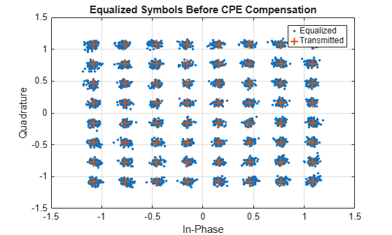
Plot the constellation before CPE compensation. The received symbols show phase rotation because of the phase noise.
figure
plot(dataEqualized,".",MarkerSize=8)
hold on
plot(pdschSym,"+",MarkerSize=10,LineWidth=1.5)
grid on
title("Equalized Symbols Before CPE Compensation")
xlabel("In-Phase")
ylabel("Quadrature")
legend("Equalized","Transmitted")
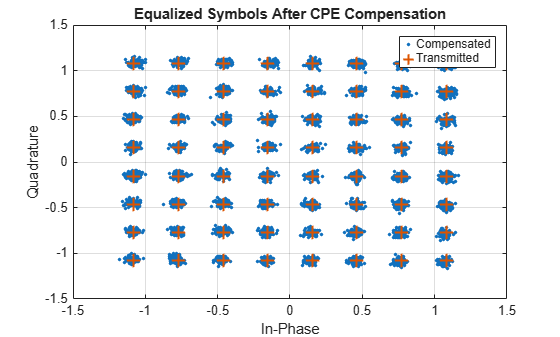
Plot constellation after CPE compensation.
figure
plot(dataOut,".",MarkerSize=8)
hold on
plot(pdschSym,"+",MarkerSize=10,LineWidth=1.5)
grid on
title("Equalized Symbols After CPE Compensation")
xlabel("In-Phase")
ylabel("Quadrature")
legend("Compensated","Transmitted")
Estimate and compensate for CPE in a DFT-s-OFDM physical uplink shared channel (PUSCH) transmission in the presence of phase noise.
To ensure simulation results are repeatable, initialize the random number generator with a fixed seed. For greater statistical accuracy, run the simulation for multiple times with different seeds and compute the average results.
rng(1)
Configure the carrier using an nrCarrierConfig object. Specify a subcarrier spacing of 60 kHz with a transmission bandwidth of 50 MHz operating in frequency range 2 (FR2).
carrier = nrCarrierConfig(NSizeGrid=66,SubcarrierSpacing=60);
Configure a transform-precoded PUSCH that occupies the complete carrier and enable PT-RS.
pusch = nrPUSCHConfig( ...
    PRBSet=0:carrier.NSizeGrid-1, ...
    SymbolAllocation=[0 carrier.SymbolsPerSlot], ...
    TransformPrecoding=true, ...
    Modulation="16QAM", ...
    EnablePTRS=true);
pusch.PTRS = nrPUSCHPTRSConfig(NumPTRSSamples=4,NumPTRSGroups=8);
Generate the PUSCH resource element indices and PT-RS reference indices, and generate the DM-RS and PT-RS reference symbols.
[puschInd,puschInfo,ptrsRefInd] = nrPUSCHIndices(carrier,pusch);
dmrsInd = nrPUSCHDMRSIndices(carrier,pusch);
dmrsSym = nrPUSCHDMRS(carrier,pusch);
ptrsRefSym = nrPUSCHPTRS(carrier,pusch);
Generate the coded bits and PUSCH symbols using the nrPUSCH function. When transform precoding is enabled, nrPUSCH multiplexes the data and PT-RS symbols before transform precoding to form the PUSCH symbol sequence.
cw = randi([0 1],puschInfo.G,1);
puschSym = nrPUSCH(carrier,pusch,cw);
Create and populate the resource grid with PUSCH and DM-RS symbols. When transform precoding is enabled, the PUSCH symbols include PT-RS information in addition to data symbols.
txGrid = nrResourceGrid(carrier);
txGrid(puschInd) = puschSym;
txGrid(dmrsInd) = dmrsSym;
Perform OFDM modulation on the transmitted waveform.
[txWaveform,ofdmInfo] = nrOFDMModulate(carrier,txGrid);
Model oscillator phase noise using the nrPhaseNoise System object™.
pnoise = nrPhaseNoise( ...
    CarrierFrequency=30e9, ...
    SampleRate=ofdmInfo.SampleRate, ...
    RandomStream="mt19937ar");
Apply oscillator phase noise to the transmit waveform and demodulate the received waveform.
rxGrid = nrOFDMDemodulate(carrier,pnoise(txWaveform));
Estimate the channel using the nrChannelEstimate function.
[estChannelGrid,noiseEst] = nrChannelEstimate(carrier,rxGrid,dmrsInd,dmrsSym,CDMLengths=pusch.DMRS.CDMLengths);
Extract and equalize the received PUSCH resource elements.
[puschRx,puschHest] = nrExtractResources(puschInd,rxGrid,estChannelGrid);
puschEq = nrEqualizeMMSE(puschRx,puschHest,noiseEst);
Perform transform de-precoding on the equalized PUSCH symbols and extract the PT-RS symbols.
numPRB = numel(puschInfo.PRBSet);
puschEqDeprecode = nrTransformDeprecode(puschEq,numPRB);
ptrsIndInPUSCH = nrPUSCHPTRSIndices(carrier,pusch);
ptrsEq = puschEqDeprecode(ptrsIndInPUSCH);
Estimate the CPE per OFDM symbol using the nrPhaseNoiseEstimate function.
cpe = nrPhaseNoiseEstimate(carrier,ptrsEq,ptrsRefInd,ptrsRefSym)
cpe = 1×14

    0.0047    0.0152    0.0043   -0.0066    0.0222    0.0003   -0.0285   -0.0128   -0.0100    0.0133    0.0246    0.0119    0.0246    0.0353
Compensate the data symbols using the nrPhaseNoiseCompensate function.
dataOut = nrPhaseNoiseCompensate(carrier,puschEq,puschInd,cpe);
Perform transform de-precoding on the compensated and reference PUSCH symbols. Then, remove the PT-RS locations from the equalized, compensated, and reference PUSCH symbols and use the remaining data symbols for EVM measurement.
puschEqCompDeprecode = nrTransformDeprecode(dataOut,numPRB);
puschRefDeprecode = nrTransformDeprecode(puschSym,numPRB);

dataEq = puschEqDeprecode;
dataEq(ptrsIndInPUSCH) = [];

dataComp = puschEqCompDeprecode;
dataComp(ptrsIndInPUSCH) = [];

dataRef = puschRefDeprecode;
dataRef(ptrsIndInPUSCH) = [];
Calculate the EVM for symbols after CPE compensation and display the relative EVM improvement.
evm_Before_CPE = nrEVM(dataEq,dataRef)
evm_Before_CPE =
0.0422
evm_After_CPE = nrEVM(dataComp,dataRef)
evm_After_CPE =
0.0390
relative_EVM_Improvement = 100*(evm_Before_CPE-evm_After_CPE)/evm_Before_CPE
relative_EVM_Improvement =
7.6200
Input Arguments
Output Arguments
Algorithms
To estimate CPE, the function executes these steps:
Estimate CPE per OFDM symbol per port:
Compute the complex correlation value for each PT‑RS subcarrier by multiplying the corresponding equalized PT‑RS symbol with the complex conjugate of the known PT‑RS symbol.
Average the complex correlation value across all PT‑RS subcarriers within the OFDM symbol.
Extract the phase of the averaged result to obtain a single CPE estimate for the OFDM symbol.
Determine CPE for OFDM symbols that do not contain PT‑RS based on the available PT‑RS symbol locations. If at least two OFDM symbols contain a PT‑RS, the function computes CPE at the missing OFDM symbol locations by interpolating between adjacent PT‑RS OFDM symbols. The function sets CPE to zero for OFDM symbols that lie outside the PT‑RS symbol range.
Extended Capabilities
Version History
Introduced in R2026b

