NR NTN PUSCH Throughput
This example measures 5G New Radio (NR) physical uplink shared channel (PUSCH) throughput over a non-terrestrial network (NTN) service link assuming a regenerative satellite payload. The example supports NTN narrowband, NTN tapped delay line (TDL), and NTN clustered delay line (CDL) propagation channels.
Introduction
NTN extend 5G coverage beyond terrestrial cellular infrastructure to remote, rural, oceanic, and under-served regions. In satellite-based NTN deployments, platforms such as low Earth orbit (LEO), medium Earth orbit (MEO), or geostationary Earth orbit (GEO) satellites integrate into the 5G architecture to provide wide-area connectivity. Depending on the payload architecture, a satellite operates in one of the two modes:
Transparent (bent-pipe) mode: Forwards the received RF signal to a gateway without onboard signal processing.
Regenerative mode: Performs signal processing functions such as demodulation and decoding onboard, implementing all or part of the gNodeB base station functionality.
NTN defines two main radio links:
Service link: Between the user equipment (UE) and the satellite.
Feeder link: Between the satellite and the gateway, based on 3GPP or non-3GPP technologies.
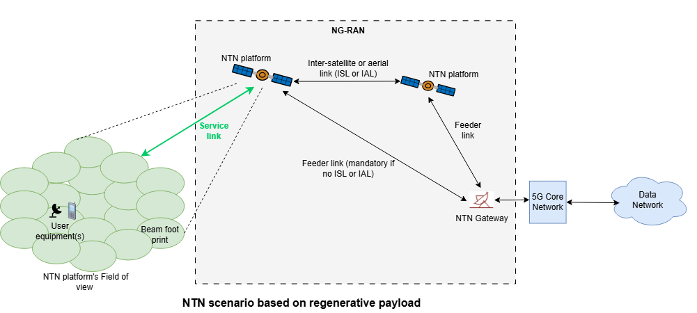
This example assumes a regenerative satellite payload as defined by 3GPP NR standards [1], [2], [3], [4], [6], and [7] and measures PUSCH throughput for the service link.
The figure shows an NTN scenario with a regenerative payload as shown in Figure 4.1-2 in 3GPP TR 38.821 [7].
The figure shows the processing chain for the 5G NTN service uplink using a regenerative satellite payload. To simplify the figure, the demodulation reference signals (DM-RS) and phase tracking reference signals (PT-RS) generation blocks are omitted.
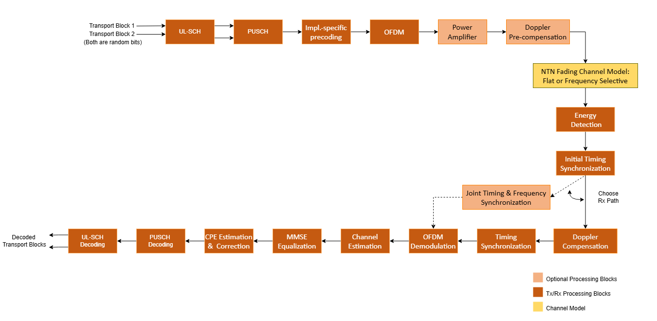
The processing blocks include:
UL-SCH (Uplink Shared Channel)
UL-SCH transport channel coding.
Multiple codewords, dependent on the number of layers.
Optional hybrid automatic repeat request (HARQ) support up to 32 processes.
PUSCH (Physical Uplink Shared Channel)
Codebook-based and non-codebook-based PUSCH transmission schemes.
PUSCH, PUSCH DM-RS, and PUSCH PT-RS generation.
Slot-wise and non-slot-wise PUSCH and DM-RS mapping.
Implementation specific precoding
Optional PUSCH transform precoding. Set the transform precoding to true for DFT-s-OFDM and false for CP-OFDM.
This example does not include closed-loop adaptation of the MIMO precoding according to channel conditions. For codebook-based transmission, the MIMO precoding matrix is selected using the TPMI parameter. For non-codebook-based transmission (or for mapping antenna ports to physical antennas in codebook-based transmission), the MIMO precoding matrix is an identity matrix.
NTN Channel Model
NTN Narrowband, NTN TDL, and NTN CDL propagation channel models.
Optional static and time-varying propagation delay modeling.
Other features of the simulation are:
Optional power amplifier modeling with and without memory. The power amplifier modeling with memory requires RF Toolbox™.
Doppler pre-compensation at the transmitter, and Doppler compensation at the receiver.
Timing synchronization and channel estimation.
To reduce the total simulation time, you can use Parallel Computing Toolbox™ to execute the range of transmit power values of the transmit power loop in parallel.
Configure Simulation Parameters
Set the simulation length in terms of the number of 10 ms frames. By default, the example uses 3 frames, but a large number of 10 ms frames is necessary to produce meaningful throughput results. For the NR NTN uplink, the UE transmit power (TxPower) represents the post power amplifier output power, before applying Doppler pre-compensation. The receiver parameters include the gain over system noise temperature (RxGByT, in dB/K) and receiver gain (RxGain, in dBi) to model the receiver noise. These parameter values align with the LEO-600 satellite characteristics specified in Table 6.1.1.1-1 of 3GPP TR 38.821 [7].
simParameters = struct;          % Create simParameters structure to
                                 % contain all key uplink simulation parameters
simParameters.NFrames = 3;       % Number of 10 ms frames
simParameters.TxPower = 18:2:30; % UE transmit power (dBm)
simParameters.RxGByT = 1.1;      % Receiver Gain over System Noise Temperature (G/T, in dB/K).
simParameters.RxGain = 30;       % Receiver Gain (G, in dBi)
Set the displaySimulationInformation variable to true to display information about the throughput simulation at each transmit power point.
displaySimulationInformation =  true;
true;Configure Carrier and PUSCH Parameters
This example uses default parameters based on the G-FR1-NTN-A3-1 scenario defined in Section 6.1.3.3.3 of 3GPP TR 38.108 [9].
% Carrier Configuration as defined in TS 38.211 Sections 4.2, 4.3, and 4.4 simParameters.Carrier = nrCarrierConfig; simParameters.Carrier.NCellID =0; % Physical layer cell identity. Range:[0, 1007] simParameters.Carrier.SubcarrierSpacing =
15; % 15 | 30 | 60 | 120 (kHz) simParameters.Carrier.CyclicPrefix =
"Normal"; % "Normal" | "Extended" (Extended CP is relevant for 60 kHz SCS only) simParameters.Carrier.NSizeGrid = 25; % 25 RBs (12 subcarriers per RB) at 15kHz SCS - 5 MHz bandwidth % PUSCH as defined in TS 38.211 Sections 6.3.1, 6.4.1.1, and 6.4.1.2 % This PUSCH definition is the basis for all PUSCH transmissions in the % throughput simulation simParameters.PUSCH = nrPUSCHConfig; simParameters.PUSCH.Modulation =
"QPSK"; % "pi/2-BPSK" | "QPSK" | "16QAM" | "64QAM" | "256QAM" simParameters.PUSCH.NumLayers =
1; % Number of transmission layers simParameters.PUSCH.MappingType =
"A"; % "A" | "B" simParameters.PUSCH.SymbolAllocation = [0,simParameters.Carrier.SymbolsPerSlot]; % Starting symbol and number of symbols of each PUSCH allocation simParameters.PUSCH.PRBSet = 0:simParameters.Carrier.NSizeGrid-1; % Full grid time-frequency resource allocation per slot simParameters.PUSCH.TransformPrecoding =
false; % true for DFT-s-OFDM, false for CP-OFDM. If transform precoding is enabled, the number of layers should be set to 1. simParameters.PUSCH.TransmissionScheme =
"nonCodebook"; % "codebook" | "nonCodebook" simParameters.PUSCH.NumAntennaPorts = 1; % Number of antenna ports for codebook-based precoding simParameters.PUSCH.NID = simParameters.Carrier.NCellID; % Scrambling identifier simParameters.PUSCH.RNTI =
1; % UE identifier simParameters.PUSCH.EnablePTRS =
false; % Enable or disable PT-RS % DM-RS and antenna port configuration as defined in TS 38.211 Section 6.4.1.1 simParameters.PUSCH.DMRS.DMRSConfigurationType =
1; % 1 | 2 simParameters.PUSCH.DMRS.DMRSTypeAPosition =
2; % 2 | 3. Set when Mapping type is A simParameters.PUSCH.DMRS.DMRSAdditionalPosition =
1; % 0 | 1 | 2 | 3. Additional DM-RS symbol positions simParameters.PUSCH.DMRS.DMRSLength =
1; % 1 | 2. Number of front-loaded DM-RS symbols simParameters.PUSCH.DMRS.NIDNSCID =
0; % Range: [0,65535]. Scrambling identity for CP-OFDM simParameters.PUSCH.DMRS.NRSID =
0; % Range: [0,1007]. Scrambling ID for low-PAPR sequences (0...1007) simParameters.PUSCH.DMRS.NSCID =
0; % 0 | 1. Scrambling initialization for CP-OFDM simParameters.PUSCH.DMRS.NumCDMGroupsWithoutData =
2; % 1 | 2 | 3 . Number of CDM groups without data simParameters.PUSCH.DMRS.GroupHopping =
0; % 0 | 1. Group hopping simParameters.PUSCH.DMRS.SequenceHopping =
0; % 0 | 1. Sequence hopping % PUSCH PT-RS configuration when PTRS is enabled as defined in TS 38.211 Section 6.4.1.2 simParameters.PUSCH.PTRS.TimeDensity =
1; % 1 | 2 | 4. PT-RS time density (L_PT-RS) simParameters.PUSCH.PTRS.FrequencyDensity =
2; % 2 | 4. PT-RS frequency density (K_PT-RS) simParameters.PUSCH.PTRS.REOffset =
"00"; % 00 | 01 | 10 | 11. PT-RS resource element offset simParameters.PUSCH.PTRS.NumPTRSGroups =
2; % 2 | 4 | 8. Number of PT-RS groups simParameters.PUSCH.PTRS.NumPTRSSamples =
2; % 2 | 4. Number of PT-RS samples per PT-RS group simParameters.PUSCH.PTRS.NID =
0; % Range: [0,1007]. PT-RS scrambling identity % This structure is to hold additional simulation parameters for the UL-SCH % and PUSCH simParameters.PUSCHExtension = struct(); simParameters.PUSCHExtension.TargetCodeRate = 308/1024; % TS 38.214 Section 6.1.4.1 simParameters.PUSCHExtension.XOverhead = 6*simParameters.PUSCH.EnablePTRS; % Set PUSCH rate matching overhead for TBS (Xoh) to 6 when PT-RS is enabled, otherwise 0 simParameters.PUSCHExtension.NHARQProcesses =
4; % Number of parallel HARQ processes to use simParameters.PUSCHExtension.EnableHARQ =
true; % Enable retransmissions for each process, using RV sequence [0,2,3,1] simParameters.PUSCHExtension.EnableCBGTransmission =
false; % Enable CBG-based transmission, otherwise TB-based transmission simParameters.PUSCHExtension.MaxNumCBG = 4; % Maximum number of CBGs per transport block for each HARQ process in CBG-based transmission simParameters.PUSCHExtension.LDPCDecodingAlgorithm =
"Normalized min-sum"; % "Belief propagation" | "Layered belief propagation" | "Normalized min-sum" | "Offset min-sum" simParameters.PUSCHExtension.MaximumLDPCIterationCount = 6; % Maximum number of LDPC iterations simParameters.PUSCHExtension.DMRSPower = 3; % The ratio of DM-RS RE power to PUSCH resource element (RE) power in dB % Define the overall transmission antenna geometry at end-points % For NTN Narrowband channel, only single-input-single-output (SISO) transmission is allowed % Number of PUSCH transmission antennas >= NumLayers simParameters.NumTransmitAntennas = 1; if simParameters.PUSCH.NumCodewords > 1 % Multi-codeword transmission simParameters.NumReceiveAntennas = 8; % Number of NTN receive antennas (even number >= NumLayers) else simParameters.NumReceiveAntennas = 1; % Number of NTN receive antennas (1 or even number >= NumLayers) end % Use these array size parameters for NTN CDL channel to model transmit and % receive antennas simParameters.TxArraySize = [1 1 1 1 1]; % [M N P Mg Ng], product of all values must be equal to NumTransmitAntennas simParameters.RxArraySize = [1 1 1 1 1]; % [M N P Mg Ng], product of all values must be equal to NumReceiveAntennas simParameters.DataType =
"double"; % Define data type for resource grids and waveforms
Get information about the baseband waveform after the OFDM modulation step.
waveformInfo = nrOFDMInfo(simParameters.Carrier);
Configure Power Amplifier
Enable or disable power amplifier (PA) modeling using EnablePA. When you enable PA modeling, the example supports two modes:
Memoryless PA modeling: Applies predefined or custom nonlinearity models.
Memory-based PA modeling: Requires RF Toolbox™ and uses polynomial coefficients to model PA behavior with memory effects. To enable memory-based PA modeling, set
HasPAMemoryto true.
Memoryless Power Amplifier
To model a memoryless PA, set the PAModel parameter to one of the predefined PA types specified in Annex A of TR 38.803 [8]. The supported models are:
2.1 GHz Gallium Arsenide (GaAs)
2.1 GHz Gallium Nitride (GaN)
28 GHz complementary metal-oxide semiconductor (CMOS)
28 GHz GaN
These PA models are provided for generic NR waveform nonlinearity evaluation. In NR NTN uplink scenarios, only the 2.1 GHz GaAs/GaN reflect realistic UE hardware. For these PA models, the memoryless nonlinearity applied to the waveform is as follows:
,
where:
is the output signal.
is the input signal.
is the set of polynomial degree(s).
is the polynomial coefficient.
Alternatively, you can set PAModel to Custom and use PACharacteristics to define the memoryless power amplifier characteristics as a matrix with three columns. The first column defines the input power in dBm. The second column defines the output power in dBm. The third column defines the output phase in degrees. When you set the PACharacteristics variable to empty and PAModel to Custom, this example uses a 2.1 GHz laterally-diffused metal-oxide semiconductor (LDMOS) Doherty-based amplifier.
Power Amplifier With Memory
The nonlinearity with memory applied to the waveform follows this polynomial equation:
In this equation:
is the memory-polynomial depth.
is the memory-polynomial degree.
is the polynomial coefficient.
To model the PA with memory, set the PACoefficients variable to provide the polynomial coefficients. The PACoefficients variable is a matrix with number of rows corresponding to memory-polynomial depth and number of columns corresponding to memory-polynomial degree. When you set PACoefficients to empty, the example uses a default 2.44 GHz memory polynomial model as defined in TR 38.803 Appendix A [8].
simParameters.EnablePA =false; % true or false simParameters.HasPAMemory =
false; % true or false % Power amplifier parameters simParameters.PAModel =
"2.1GHz GaAs"; % "2.1GHz GaAs", "2.1GHz GaN", "28GHz CMOS", "28GHz GaN", or "Custom" simParameters.PACharacteristics = []; % Lookup table as empty or a matrix with columns: Pin (dBm) | Pout (dBm) | Phase (degrees) simParameters.PACoefficients = []; % Memory polynomial coefficients
The input signal passed to the power amplifier is normalized to its maximum amplitude. Use the PAScaleFactor variable to modify the maximum input signal amplitude to excite the power amplifier nonlinearity. PAScaleFactor controls the operating region of the power amplifier and is applied to each transmit antenna. You can also use the PAScaleFactor variable to set power backoff. For example, to provide a power backoff of 3 dB to a signal passed through the power amplifier, set PAScaleFactor to -3. Ensure that the input signal is within the characterization range of the power amplifier model.
When PAScaleFactor is empty, the example uses a default value of -35 dB in these cases:
HasPAMemoryisfalse,PAModelisCustom, andPACharacteristicsis empty.HasPAMemoryistrueandPACoefficientsis empty.
In all other cases, when you set PAScaleFactor to empty, the example uses a default value of 0 dB.
simParameters.PAScaleFactor = []; % Amplitude scaling, in dBConfigure Doppler Compensation
The example supports Doppler compensation at both the transmitter and the receiver. Transmitter Doppler compensation applies pre-compensation to the transmitted waveform to correct for Doppler shift caused by satellite and UE movement. Receiver Doppler compensation corrects the residual Doppler shift of the received waveform using the cyclic prefix and reference signals. You can specify the technique for Doppler estimation and compensation at the receiver using the RxDopplerCompensationMethod field. The RxDopplerCompensationMethod field supports:
Independent time-frequency synchronization (
independent time-freq), where the receiver compensates for frequency or Doppler shift first and then compensates for timing offset.Joint time-frequency synchronization (
joint time-freq), where the receiver compensates for both frequency and time at once.
% Doppler compensation parameters simParameters.RxDopplerCompensationMethod ="independent time-freq"; % Set the search range of Doppler shift in Hz [MIN,MAX] simParameters.FrequencyRange = [-50e3 50e3]; % Set the search range resolution of Doppler shift in Hz simParameters.FrequencyResolution = 1e3;
Configure UE and Satellite Position and Velocity
NTN supports two UE categories: with global navigation satellite system (GNSS) support and without GNSS support. For UEs equipped with GNSS, refer to the GPS Legacy Navigation Receiver Positioning Using C/A-Code (Satellite Communications Toolbox) example to estimate the UE position. In scenarios where the GNSS signal is weak, or unavailable, or where the receiver does not have a GNSS module, use the Receiver Position Estimation Using Range and Range-Rate Measurements in NTN Systems (Satellite Communications Toolbox) example to estimate the UE position. In this example, the initial positions and velocities of the UE are specified directly in Earth-Centered Earth-Fixed (ECEF) coordinates.
In NR NTN systems, the UE requires satellite position and velocity information to pre-compensate the Doppler shift. The NTN gNodeB shares the satellite ephemeris information in system information block SIB19 to the UE for NTN access. Ephemeris is expressed either using a position and velocity state vector in ECEF or using orbital parameters in Earth-Centered Inertial (ECI). This example uses ephemeris data in the form of orbital parameters. The parameters defining the orbit are semi-major axis, eccentricity, inclination, right ascension of the ascending node, argument of periapsis, and true anomaly.
By default, this example models a typical NTN scenario in which a ground-based UE communicates with a LEO satellite in a circular polar orbit. The scenario starts at 12:10:18 UTC on December 3, 2025, and runs for 60 seconds. The UE is positioned near the Earth's surface, with a velocity vector representing a slowly moving ground terminal. These default values enable realistic modeling of Doppler effects, propagation delay, and dynamic link geometry as the satellite moves along its circular orbit.
% Satellite scenario simulation parameters
simParameters.ScenarioStartTime = datetime(2025,12,3,12,10,18,'TimeZone','UTC');
simParameters.ScenarioRunTime = 60; % in seconds

% UE position and velocity
simParameters.UEPosition = [-2325213.67; 5933245.99; 265303.05]; % ECEF coordinates [x,y,z] in m
simParameters.UEVelocity = [-0.977; 0.213; 0];                   % ECEF coordinates [x,y,z] in m/s

% Satellite orbital parameters
simParameters.SemiMajorAxis = 6971000; % in meters (altitude ≈ 600 km above Earth's surface)
simParameters.Eccentricity = 0;        % Circular
simParameters.Inclination = 90;        % degrees
simParameters.RAAN = 0;                % degrees
simParameters.Argofperiapsis = 0;      % degrees
simParameters.TrueAnomaly = 0;         % degrees (satellite's position in its orbit at scenario start)
Configure NTN Propagation Channel Model
Create the channel model object for the simulation by setting the NTNChannelType property to select from the Narrowband, TDL, and CDL channel models as described in [5], [6]. For more information on how to model these channels, see Model NR NTN Channel (Satellite Communications Toolbox). To include free-space path loss in the simulation, set EnablePathLoss to true. Specify the carrier frequency for the NTN channel using the CarrierFrequency property, for example, S-band (1980–2010 MHz) or Ka-band (29.5–30.0 GHz), as defined in 3GPP TS 38.811 Section 5.2 [6].
% Define the general NTN propagation channel parameters simParameters.NTNChannelType ="Narrowband"; % "Narrowband" | "TDL" | "CDL" % Enable or disable free space path loss simParameters.EnablePathLoss =
true; % Enable or disable satellite Doppler shift simParameters.EnableDoppler =
true; % Enable or disable modeling of propagation delay simParameters.EnableDelay =
false; % Link variation model configuration. Controls how path loss, Doppler % shift, and propagation delay are updated during the simulation. This % example models only one-way propagation delay and provides immediate % feedback without any delay. Set this parameter if any of EnablePathLoss, % EnableDoppler, or EnableDelay is set to true. simParameters.LinkVariationModel =
"Static"; % "Static" | "Time-varying" % Set the parameters common to NTN channels simParameters.CarrierFrequency = 2e9; % Carrier frequency (in Hz) simParameters.OutputDataType = simParameters.DataType; % Channel type specific parameter configuration if simParameters.NTNChannelType == "Narrowband" simParameters.Environment =
"Urban"; simParameters.AzimuthOrientation = 0; elseif (simParameters.NTNChannelType == "TDL" || simParameters.NTNChannelType == "CDL") simParameters.DelayProfile = "NTN-"+ simParameters.NTNChannelType +
"-A"; simParameters.DelaySpread = 30e-9; % seconds (TS 38.901 Section 7.7.3) end % Validate PUSCH layering against the channel geometry HelperNRNTNThroughput.validateNumLayers(simParameters);
Select Initial Timing Synchronization Algorithm
Select an algorithm for initial timing synchronization.
Auto correlation (
auto corr): The receiver performs timing synchronization using auto correlation with PUSCH DM-RS.Differential correlation (
diff corr): The receiver performs timing synchronization using differential correlation with PUSCH DM-RS.Joint time-frequency technique (
joint time-freq): The receiver performs timing synchronization by compensating for initial frequency and initial timing at once.
% Timing Synchronization parameters simParameters.InitialTimingSynchronization ="joint time-freq"; % The example uses below fields to perform initial synchronization, when % InitialTimingSynchronization is set to joint time-freq. % Set the initial search range of Doppler shift in Hz [MIN,MAX] simParameters.InitialFrequencyRange = [-50e3 50e3]; % Set the initial search range resolution of Doppler shift in Hz simParameters.InitialFrequencyResolution = 1e3;
Initialization
% Compute the access intervals between a moving user equipment (UE) and a
% satellite and find the earliest feasible satellite access start time. For
% each slot beginning at the access start time, calculate elevation, path
% loss, Doppler, and delay
slotParams = HelperNRNTNThroughput.computeAccessSlotParameters(simParameters, waveformInfo);
Access interval table (periods when satellite is visible to UE):
       Source        Target    IntervalNumber         StartTime                EndTime           Duration    StartOrbit    EndOrbit
    _____________    ______    ______________    ____________________    ____________________    ________    __________    ________

    "Satellite 1"     "UE"           1           03-Dec-2025 12:10:18    03-Dec-2025 12:11:18       60           1            1

Transmission start time : 03-Dec-2025 12:10:18 UTC
% Check the number of HARQ processes and initial propagation delay
initialSlotDelay = find(seconds(slotParams.SlotTimes-slotParams.AccessStartTime)>=slotParams.DelayInSeconds(1),1)-1;
if simParameters.PUSCHExtension.EnableHARQ
    if simParameters.PUSCHExtension.NHARQProcesses < initialSlotDelay
        error("In case of HARQ, this example supports transmission of continuous data only. " + ...
            "Set the number of HARQ processes (" + (simParameters.PUSCHExtension.NHARQProcesses) +...
            ") to a value greater than or equal to the maximum propagation delay in slots (" + ...
            initialSlotDelay +").")
    end
end

% Initialize objects to model delay
delayObjInfo = HelperNRNTNThroughput.initializeDelayObjects(simParameters,waveformInfo,slotParams.DelayInSeconds);

% Compute the noise power per receive antenna
kBoltz = physconst("boltzmann");
NTemp = simParameters.RxGain - simParameters.RxGByT;
NTemp_amp = 10^(NTemp/10); % Linear scale
noisePow = kBoltz*waveformInfo.SampleRate*NTemp_amp;

% Set up RV sequence for all HARQ processes
if simParameters.PUSCHExtension.EnableHARQ
    rvSeq = [0 2 3 1];
else
    rvSeq = 0;
end

% Set up maximum number of CBGs in retransmission
if simParameters.PUSCHExtension.EnableCBGTransmission
    maxNumCBG = simParameters.PUSCHExtension.MaxNumCBG;
else
    maxNumCBG = 1;
end

% Create UL-SCH encoder System object to perform transport channel encoding
encodeULSCH = nrULSCH;
encodeULSCH.MultipleHARQProcesses = true;
encodeULSCH.CBGTransmission = true;
encodeULSCH.TargetCodeRate = simParameters.PUSCHExtension.TargetCodeRate;

% Create UL-SCH decoder System object to perform transport channel decoding
decodeULSCH = nrULSCHDecoder;
decodeULSCH.MultipleHARQProcesses = true;
decodeULSCH.CBGTransmission = true;
decodeULSCH.TargetCodeRate = simParameters.PUSCHExtension.TargetCodeRate;
decodeULSCH.LDPCDecodingAlgorithm = simParameters.PUSCHExtension.LDPCDecodingAlgorithm;
decodeULSCH.MaximumLDPCIterationCount = ...
    simParameters.PUSCHExtension.MaximumLDPCIterationCount;

% Initialize the power amplifier function handle or System object depending
% on the input configuration
[hpa,hpaDelay,paInputScaleFactor] = ...
    HelperNRNTNThroughput.initializePA(simParameters.PAModel,simParameters.HasPAMemory,simParameters.PACharacteristics,simParameters.PACoefficients);
% Repeat hpa to have independent processing for each antenna
hpa = repmat({hpa},1,simParameters.NumTransmitAntennas);
% Update the power amplifier input scaling factor, based on PAScaleFactor
if ~isempty(simParameters.PAScaleFactor)
    paInputScaleFactor = simParameters.PAScaleFactor;
end

% Initial frequency shift search space
if simParameters.InitialTimingSynchronization == "joint time-freq"
    inifVals = simParameters.InitialFrequencyRange(1):simParameters.InitialFrequencyResolution:simParameters.InitialFrequencyRange(2);
else
    inifVals = 0;
end

% Frequency shift search space
if simParameters.RxDopplerCompensationMethod == "joint time-freq"
    fVals = simParameters.FrequencyRange(1):simParameters.FrequencyResolution:simParameters.FrequencyRange(2);
else
    fVals = 0;
end

dtxThresold = 0.48;       % Threshold value to detect the valid OFDM symbol boundary.
sampleDelayOffset = 0;    % Offset to account for the common delay
usePreviousShift = false; % Set to true to use the shift value estimated in first slot directly.
useDiffCorr = true;       % Use the shift estimated from differential correlation directly in the integer Doppler shift estimation.
amplThreshold = 1.03;     % Amplitude scaling factor to use in energy detection.

% Use the minimum number of samples for a slot in the whole frame as
% window length
mrms = dsp.MovingRMS;
slotsPerSubFrameFlag = simParameters.Carrier.SlotsPerSubframe > 1;
symLen = cumsum(waveformInfo.SymbolLengths); % Lengths of each OFDM symbol in a slot
mrms.WindowLength = symLen((1+(slotsPerSubFrameFlag))*simParameters.Carrier.SymbolsPerSlot) ...
    -slotsPerSubFrameFlag*symLen(simParameters.Carrier.SymbolsPerSlot);

if (strcmpi(simParameters.PUSCH.TransmissionScheme,'codebook'))
    % Codebook-based MIMO precoding, F precodes between PUSCH
    % transmit antenna ports and transmit antennas
    F = eye(simParameters.PUSCH.NumAntennaPorts,simParameters.NumTransmitAntennas);
else
    % Non-codebook-based MIMO precoding, F precodes between PUSCH
    % layers and transmit antennas
    F = eye(simParameters.PUSCH.NumLayers,simParameters.NumTransmitAntennas);
end
txSize = size(F,1);

% Compute the number of slots
NSlots = simParameters.NFrames*simParameters.Carrier.SlotsPerFrame;

% Define NTN channel based on the specified fields in simParameters
% structure and compute maximum channel delay
[chan, maxChDelay, ueDoppler] = HelperNRNTNThroughput.configureNTNChannel(simParameters,slotParams.ElevationAngle,waveformInfo.SampleRate);

numTxPowerPoints = length(simParameters.TxPower);
maxThroughput = zeros(numTxPowerPoints,1);
simThroughput = zeros(numTxPowerPoints,1);
snrVec = zeros(numTxPowerPoints,1);
snrdb = zeros(numTxPowerPoints,1);
Processing Loop
To determine the throughput at each transmit power point, analyze the PUSCH data for each transmission instance using these steps.
Generate the transport block — Check the transmission status of the specified HARQ process to determine if retransmission is required. If retransmission is not needed, get the transport block size for each codeword depending on the PUSCH configuration and generate new data.
Generate the resource grid — Perform transport channel coding using the
nrULSCHSystem object™. The object operates on the input transport block and maintains an internal copy for potential retransmissions. Modulate the encoded data bits using thenrPUSCHfunction. Apply implementation-specific multiple-input-multiple-output (MIMO) precoding to the modulated symbols. IfTxSchemeis set to'codebook', note thatnrPUSCHalready applies codebook-based MIMO precoding internally and the implementation-specific precoding is an additional stage. Finally, map the precoded symbols and reference signals to the resource grid.Generate the waveform — The
nrOFDMModulatefunction provides the time-domain waveform by performing OFDM modulation of the generated resource grid. Normalize the waveform with the maximum waveform amplitude for each antenna.Apply power amplifier nonlinearities — Scale the amplitude of normalized waveform depending on the input scaling factor. Apply the memory or memoryless power amplifier nonlinearities to the baseband OFDM waveform. Scale the waveform power to the desired transmit power.
Apply Doppler pre-compensation — Apply the Doppler shift due to satellite and UE movement to the generated waveform to pre-compensate the channel induced Doppler shift.
Model and apply a noisy channel — Delay the generated waveform depending on the propagation latency. Pass the delayed waveform through an NTN narrowband, NTN TDL, or NTN CDL fading channel to get the faded waveform. Apply path loss and add thermal noise to the faded waveform.
Perform initial synchronization — Check the presence of the signal using energy detection. After energy detection, the received waveform uses the PUSCH DM-RS of the initial slot to get the initial timing offset. Perform this step till the initial synchronization is achieved.
Apply Doppler compensation — Estimate the Doppler shift in the received waveform and compensate the Doppler shift.
Perform synchronization and OFDM demodulation — For timing synchronization, the received waveform is correlated with the PUSCH DM-RS. The
nrOFDMDemodulatefunction then OFDM-demodulates the synchronized signal.Perform channel estimation — For channel estimation, PUSCH DM-RS is used.
Perform equalization and CPE compensation — The
nrEqualizeMMSEfunction equalizes the received PUSCH REs. Use the PT-RS symbols to estimate the common phase error (CPE) and then correct the error in each OFDM symbol within the range of the reference PT-RS OFDM symbols.Decode the PUSCH — Demodulate and descramble the equalized PUSCH symbols, along with a noise estimate using the
nrPUSCHDecodefunction to obtain an estimate of the received codewords.Decode the UL-SCH and update the HARQ process with the block CRC error — Pass the decoded soft bits through the
nrULSCHDecoderSystem object. The object decodes the codeword and returns the block cyclic redundancy check (CRC) error. Update the HARQ process with the CRC error. This example determines the throughput of the PUSCH link using the CRC error.
for txPowIdx = 1:numTxPowerPoints% Comment out for parallel computing
% parfor txPowIdx = 1:numTxPowerPoints % Uncomment for parallel computing
    % To reduce the total simulation time, you can execute this loop in
    % parallel by using Parallel Computing Toolbox features. Comment
    % out the for-loop statement and uncomment the parfor-loop statement.
    % If Parallel Computing Toolbox is not installed, parfor-loop defaults
    % to a for-loop statement. Because the parfor-loop iterations are
    % executed in parallel in a nondeterministic order, the simulation
    % information displayed for each transmit power point can be intertwined.
    % To switch off the simulation information display, set the
    % displaySimulationInformation variable (defined earlier in this
    % example) to false.

    % Reset the random number generator so that each transmit power point
    % experiences the same noise realization
    rng(0,"twister");

    % Make copies of the parameter structures so that they are not Parallel
    % Computing Toolbox broadcast variables when using parfor
    simLocal = simParameters;
    waveinfoLocal = waveformInfo;
    carrier = simLocal.Carrier;
    rxCarrier = carrier;
    pusch = simLocal.PUSCH;
    puschextra = simLocal.PUSCHExtension;
    decodeULSCHLocal = decodeULSCH;
    decodeULSCHLocal.reset();

    % Make copies of intermediate variables to have warning-free execution
    % with Parallel Computing Toolbox
    delayParams = delayObjInfo;
    slot_Params = slotParams;
    thres = dtxThresold;
    sampleOffset = sampleDelayOffset;
    usePrevShift = usePreviousShift;
    useDiffCorrFlag = useDiffCorr;
    noisePower = noisePow;
    fValsVec = fVals;
    inifValsVec = inifVals;
    threshFactor = amplThreshold;
    initialDelay = initialSlotDelay;
    maxDopplerUE = ueDoppler;

    % Initialize temporary variables
    offset = 0;
    shiftOut = 0;
    txHarqProc = 0;
    rxHarqProc = 0;
    prevWave = [];
    pathFilters = [];
    rxBuff = [];
    syncCheck = true;

    % Reset the channel so that each transmit power point experiences the
    % same channel realization
    channel = chan;
    reset(channel);

    % Create PUSCH object configured for the non-codebook transmission
    % scheme, used for receiver operations that are performed with respect
    % to the PUSCH layers
    puschNonCodebook = pusch;
    puschNonCodebook.TransmissionScheme = 'nonCodebook';

    % Reset the power amplifier
    for numHPA = 1:numel(hpa)
        if ~isa(hpa{numHPA},"function_handle")
            reset(hpa{numHPA})
        end
    end

    % Reset the delay objects
    reset(delayParams.StaticDelay)
    if isa(delayParams.VariableIntegerDelay,"dsp.VariableIntegerDelay")
        reset(delayParams.VariableIntegerDelay)
    end
    if isa(delayParams.VariableFractionalDelay,"dsp.VariableFractionalDelay")
        reset(delayParams.VariableFractionalDelay)
    end

    % Reset the moving RMS object
    reset(mrms)

    % Transmit power value in dBm
    txPowerdBm = simLocal.TxPower(txPowIdx);
    txPowerdBw = txPowerdBm-30;

    % Specify the order in which we cycle through the HARQ process
    % identifiers
    harqSequence = 0:puschextra.NHARQProcesses-1;

    % Initialize the state of all HARQ processes
    % Create a parallel array of all HARQ processes
    harqEntity = cell(puschextra.NHARQProcesses,1);
    for harqId = 1:puschextra.NHARQProcesses
        harqEntity{harqId} = HARQEntity(harqSequence(harqId),rvSeq,pusch.NumCodewords,maxNumCBG);
    end

    % Loop over the entire waveform length
    for nslot = 0:NSlots-1

        % Update carrier slot number to account for new slot transmission
        carrier.NSlot = nslot;
        harqProc = harqEntity{txHarqProc+1};

        % Calculate the transport block sizes for the transmission in the slot
        trBlkSizes = nrTBS(pusch,puschextra.TargetCodeRate,puschextra.XOverhead,carrier);

        % Set transport block depending on the HARQ process
        for cwIdx = 1:pusch.NumCodewords
            % Create a new UL-SCH transport block for new data in the
            % current process
            if harqProc.NewData(cwIdx)
                trBlk = randi([0 1],trBlkSizes(cwIdx),1,'int8');
                setTransportBlock(encodeULSCH,trBlk,BlockID=cwIdx-1, ...
                    HARQID=harqProc.HARQProcessID);
                % Flush decoder soft buffer explicitly for any new data
                % because of previous RV sequence time out
                if harqProc.SequenceTimeout(cwIdx)
                    resetSoftBuffer(decodeULSCHLocal,BlockID=cwIdx-1, ...
                        HARQID=harqProc.HARQProcessID);
                end
            end
        end

        % Create a structure with transport block encoder to generate PUSCH
        % waveform
        ulsch = struct(Encoder = encodeULSCH, ...
            RedundancyVersion = harqProc.RedundancyVersion, ...
            HARQProcessID = harqProc.HARQProcessID, ...
            CBGTI = harqProc.CBGTI);

        % Generate time-domain waveform
        txWaveform0 = HelperNRNTNThroughput.generatePUSCHWaveform( ...
            carrier,pusch,ulsch,F,simLocal.PUSCHExtension.DMRSPower,simLocal.DataType);

        % Normalize the waveform with maximum waveform amplitude
        txWaveform = txWaveform0;
        txWaveform(:,1:txSize) = txWaveform0(:,1:txSize)./max(abs(txWaveform0(:,1:txSize)));

        % Power amplifier and scaling
        if (simLocal.EnablePA == 1)
            % Scale the amplitude of the waveform, as applicable
            txWaveform = txWaveform.*db2mag(paInputScaleFactor);

            % Pass the adjusted waveform through the power amplifier
            for colIdx = 1:size(txWaveform,2)
                hpaTemp = hpa{colIdx};
                txWaveform(:,colIdx) = hpaTemp(txWaveform(:,colIdx));
            end
        end

        % Scale the waveform power based on the input transmit power
        wavePower = pow2db(sum(var(txWaveform(:,1:txSize))));
        powerScaling = txPowerdBw-wavePower;      % in dB
        txWaveform = db2mag(powerScaling)*txWaveform;

        % Apply Doppler pre-compensation
        txWaveform = HelperNRNTNThroughput.compensateDopplerShift(...
            txWaveform,channel.SampleRate, ...
            slot_Params.PreCompDopplerShift(carrier.NSlot+1),true);

        % Apply path loss to the signal
        txWaveform = txWaveform*db2mag(-slotParams.PathLoss(carrier.NSlot+1));

        % Apply fixed or static delay
        delayedTx = delayParams.StaticDelay(txWaveform);
        % Apply variable integer delay
        if isa(delayParams.VariableIntegerDelay,"dsp.VariableIntegerDelay")
            delayedTx = delayParams.VariableIntegerDelay(delayedTx, ...
                cast(delayParams.NumVariableIntegerDelaySamples(carrier.NSlot+1),class(delayedTx)));
        end
        % Apply variable fractional delay
        if isa(delayParams.VariableFractionalDelay,"dsp.VariableFractionalDelay")
            delayedTx = delayParams.VariableFractionalDelay(delayedTx, ...
                cast(delayParams.NumVariableFractionalDelaySamples(carrier.NSlot+1),class(delayedTx)));
        end

        % Pass the waveform through the channel
        txWaveform = delayedTx;
        if simLocal.NTNChannelType~="CDL"
            channel.SatelliteDopplerShift = slot_Params.SatelliteDopplerShift(carrier.NSlot+1);
        else
            channel.MaximumDopplerShift = [slot_Params.SatelliteDopplerShift(carrier.NSlot+1) maxDopplerUE]; % [Rx_Sat Tx_UE]
        end
        rxWaveform = channel(txWaveform);
        rxWaveform = rxWaveform.*db2mag(simParameters.RxGain);

        % Add thermal noise to the received time-domain waveform.
        noise = wgn(size(rxWaveform,1),size(rxWaveform,2),noisePower,1,"linear","complex");
        sigPowerRE = sum(var(rxWaveform))*((waveinfoLocal.Nfft)^2/(carrier.NSizeGrid*12));
        noisePowerRE = sum(var(noise))*(waveinfoLocal.Nfft);
        snrVec(txPowIdx) = snrVec(txPowIdx) + sigPowerRE./noisePowerRE;
        rxWaveform = rxWaveform + noise;

        % Update the transmit HARQ process number
        if puschextra.EnableHARQ
            txHarqProc = mod(txHarqProc+1,puschextra.NHARQProcesses);
        end

        % Compute the moving RMS of the signal and perform energy detection
        % for initial synchronization
        metric = mrms(complex(rxWaveform));
        idx = metric > (sqrt(noisePower)*threshFactor);
        if ~any(idx(:)) && (rxCarrier.NSlot == 0)
            % Store the waveform that didn't pass the metric to use for
            % initial synchronization
            prevWave = rxWaveform;
            continue;
        end
        % Provide a warning when initial synchronization is missed
        if (rxCarrier.NSlot == 0) && syncCheck
            syncCheck = false;
            if (carrier.NSlot > initialDelay)
                warning("Initial slot synchronization is missed for transmit power of %d dBm. " + ...
                    "This can cause failure of all the slots. " + ...
                    "For proper synchronization, increase the transmit power.",txPowerdBm)
            end
        end

        % Buffer all the valid signal such that the length of 3 slots is
        % used for initial synchronization, and some portion of previous
        % slot is used for next slot.
        rxBuff = [rxBuff;prevWave;rxWaveform]; %#ok<AGROW>
        prevWave = [];
        if (size(rxBuff,1) < (3*(mrms.WindowLength))) && (rxCarrier.NSlot == 0)
            continue
        else
            % Here onwards reception happens continuously rxCarrier

            % Use the whole buffered waveform for receiver and generate the
            % reference signals for this particular slot to use for
            % waveform processing.
            rxData = rxBuff;
            refDMRSSymbols = db2mag(simLocal.PUSCHExtension.DMRSPower)*nrPUSCHDMRS(rxCarrier,puschNonCodebook);
            refDMRSIndices = nrPUSCHDMRSIndices(rxCarrier,puschNonCodebook);
        end

        % Gather the number of samples to be processed in current
        % receiver slot.
        % 1. Find the number of cyclic prefix samples used in the current
        % receiver slot and sum of all samples
        % 2. Add the FFT size corresponding to number of OFDM symbols
        % in current slot with the resultant value in step 1
        cpl = circshift(waveinfoLocal.CyclicPrefixLengths,-rxCarrier.NSlot*rxCarrier.SymbolsPerSlot);
        numSamplesInRxSlot = waveinfoLocal.Nfft*rxCarrier.SymbolsPerSlot + sum(cpl(1:rxCarrier.SymbolsPerSlot));

        % Perform initial time synchronization
        dmrsParams = struct(DMRSIndices = refDMRSIndices, DMRSSymbols = refDMRSSymbols);
        if rxCarrier.NSlot == 0
            initialOffset = HelperNRNTNThroughput.estimateInitialTimingOffset( ...
                rxCarrier,rxData,dmrsParams,simLocal.InitialTimingSynchronization,inifValsVec);
            d = min(delayParams.MaxVariablePropDelay,initialOffset);
        else
            initialOffset = 0;
            d = 0;
        end

        % From the starting position provided by initial offset, consider
        % the length of received waveform such that all the delays due to
        % channel, power amplifier, and propagation distance are covered.
        totalDelay = maxChDelay+delayParams.MaxVariablePropDelay+hpaDelay;
        endIdx = initialOffset+numSamplesInRxSlot+totalDelay;
        if endIdx > size(rxData,1)
            endIdx = size(rxData,1);
        end
        rxWaveform = rxData(initialOffset+1:endIdx,:);
        % Update the buffer with portion of present slot data to process
        % the next slot
        rxBuff = rxData(initialOffset-d+(numSamplesInRxSlot+1):end,:);

        % Perform Doppler compensation at the receiver
        rxDopplerParams = struct(CompensationMethod = simLocal.RxDopplerCompensationMethod, ...
            RxCarrier = rxCarrier, FreqSearchRange = fValsVec, Threshold = thres, ...
            UsePrevShift = usePrevShift, SampleOffset = sampleOffset, ...
            Shift = shiftOut-sampleOffset, UseDiffCorrFlag = useDiffCorrFlag, TotalDelay = totalDelay);
        [rxWaveform,offsetVal,shiftOut] = HelperNRNTNThroughput.compensateRxDoppler(rxWaveform, rxDopplerParams, dmrsParams, waveinfoLocal);
        if ~isempty(offsetVal)
            offset = offsetVal;
        end

        if ~(simLocal.RxDopplerCompensationMethod == "joint time-freq")
            % For timing synchronization, correlate the received waveform with
            % the PUSCH DM-RS to give timing offset estimate t and correlation
            % magnitude mag. The function hSkipWeakTimingOffset is used to
            % update the receiver timing offset. If the correlation peak in mag
            % is weak, the current timing estimate t is ignored and the
            % previous estimate offset is used.
            [t,mag] = nrTimingEstimate(rxCarrier,rxWaveform, ...
                refDMRSIndices,refDMRSSymbols);
            offset = hSkipWeakTimingOffset(offset,t,mag);
        end

        rxWaveform = rxWaveform(1+offset:end,:);
        if size(rxWaveform,1) > numSamplesInRxSlot
            rxWaveform = rxWaveform(1:numSamplesInRxSlot,:);
        end

        % Initialize parameters for bit recovery
        harqProc = harqEntity{rxHarqProc+1};
        decodeULSCHLocal.TransportBlockLength = trBlkSizes;
        ulschDecParams = struct(Decoder = decodeULSCHLocal, ...
            RedundancyVersion = harqProc.RedundancyVersion, ...
            HARQProcessID = harqProc.HARQProcessID, ...
            CBGTI = harqProc.CBGTI);

        % Recover bits from the received waveform
        [decbits,blkerr,cbgerr,rxInfo] = HelperNRNTNThroughput.recoverPUSCHBits(rxWaveform,rxCarrier,dmrsParams,puschNonCodebook,ulschDecParams);

        % Store values to calculate throughput
        simThroughput(txPowIdx) = simThroughput(txPowIdx) + sum(~blkerr .* trBlkSizes);
        maxThroughput(txPowIdx) = maxThroughput(txPowIdx) + sum(trBlkSizes);

        % Update current process with CRC error and increment slot number
        updateProcess(harqEntity{rxHarqProc+1},blkerr,trBlkSizes,rxInfo.G,cbgerr);
        rxCarrier.NSlot = rxCarrier.NSlot + 1;

        % Increment the receiver HARQ process number
        if puschextra.EnableHARQ
            rxHarqProc = mod(rxHarqProc+1,puschextra.NHARQProcesses);
        end

    end

    % Display the results
    if displaySimulationInformation == 1
        snrdb(txPowIdx) = pow2db(snrVec(txPowIdx)./NSlots);
        if rxCarrier.NSlot == 0
            fprintf("\nNo slot is processed in the receiver at transmit power %d dBm (modeled SNR per RE %.4f dB)", ...
                txPowerdBm,snrdb(txPowIdx));
        else
            fprintf("\nThroughput(Mbps) for %d frame(s) at transmit power %d dBm (modeled SNR per RE %.4f dB): %.4f\n",...
                simLocal.NFrames,txPowerdBm,snrdb(txPowIdx),1e-6*simThroughput(txPowIdx)/(simLocal.NFrames*10e-3));
            fprintf("Throughput(%%) for %d frame(s) at transmit power %d dBm (modeled SNR per RE %.4f dB): %.4f\n",...
                simLocal.NFrames,txPowerdBm,snrdb(txPowIdx),simThroughput(txPowIdx)*100/maxThroughput(txPowIdx));
        end
    end
end
Throughput(Mbps) for 3 frame(s) at transmit power 18 dBm (modeled SNR per RE -7.9035 dB): 0.0000
Throughput(%) for 3 frame(s) at transmit power 18 dBm (modeled SNR per RE -7.9035 dB): 0.0000
Throughput(Mbps) for 3 frame(s) at transmit power 20 dBm (modeled SNR per RE -5.9035 dB): 0.0717
Throughput(%) for 3 frame(s) at transmit power 20 dBm (modeled SNR per RE -5.9035 dB): 3.5714
Throughput(Mbps) for 3 frame(s) at transmit power 22 dBm (modeled SNR per RE -3.9047 dB): 0.1435
Throughput(%) for 3 frame(s) at transmit power 22 dBm (modeled SNR per RE -3.9047 dB): 7.1429
Throughput(Mbps) for 3 frame(s) at transmit power 24 dBm (modeled SNR per RE -1.9053 dB): 0.4304
Throughput(%) for 3 frame(s) at transmit power 24 dBm (modeled SNR per RE -1.9053 dB): 21.4286
Throughput(Mbps) for 3 frame(s) at transmit power 26 dBm (modeled SNR per RE 0.0971 dB): 0.7173
Throughput(%) for 3 frame(s) at transmit power 26 dBm (modeled SNR per RE 0.0971 dB): 35.7143
Throughput(Mbps) for 3 frame(s) at transmit power 28 dBm (modeled SNR per RE 2.0982 dB): 1.5781
Throughput(%) for 3 frame(s) at transmit power 28 dBm (modeled SNR per RE 2.0982 dB): 78.5714
Throughput(Mbps) for 3 frame(s) at transmit power 30 dBm (modeled SNR per RE 4.0972 dB): 2.0085
Throughput(%) for 3 frame(s) at transmit power 30 dBm (modeled SNR per RE 4.0972 dB): 100.0000
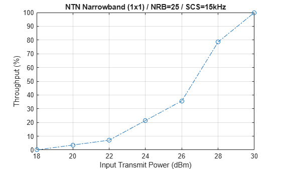
Results
Display the measured throughput, which is the percentage of the maximum possible throughput of the link given the available resources for data transmission.
figure;
plot(simParameters.TxPower,simThroughput*100./maxThroughput,'o-.')
xlabel('Input Transmit Power (dBm)'); ylabel('Throughput (%)'); grid on;
title(sprintf('NTN %s (%dx%d) / NRB=%d / SCS=%dkHz', ...
simParameters.NTNChannelType,simParameters.NumTransmitAntennas, ...
simParameters.NumReceiveAntennas,simParameters.Carrier.NSizeGrid,...
simParameters.Carrier.SubcarrierSpacing));
% Bundle key parameters and results into a combined structure for recording
simResults.simParameters = simParameters;
simResults.simThroughput = simThroughput;
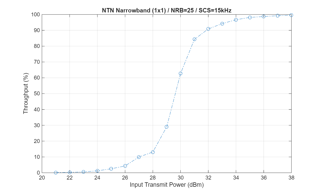
simResults.maxThroughput = maxThroughput;This next figure shows the throughput results obtained by simulating 1000 frames (NFrames = 1000, TxPower = 20:40) for a carrier with a 15 kHz SCS occupying a 5 MHz transmission bandwidth. The simulation setup includes the default carrier and PUSCH configuration with an NTN narrowband channel.
Further Exploration
You can use this example to further explore these options:
To check the throughput performance of different scenarios, change the carrier numerology and the number of transmit and receive antennas, and set the channel model type to TDL or CDL.
To check the throughput performance in the time-varying channel, set the
LinkVariationModelto"Time-varying".To compare the throughput performance in an NTN and terrestrial network, use the
nrTDLChanneland thenrCDLChannelchannel objects as shown in NR PUSCH Throughput.To analyze the throughput at each transmit power for a different satellite orbit, vary the satellite orbital parameters. To configure an elliptical orbit, set the eccentricity to a value greater than zero depending on how elongated you want the orbit. Adjust the argument of periapsis and true anomaly to define the orientation and starting position within the ellipse. For real satellite orbits, you can import orbital parameters from a TLE (Two-Line Element) file using a suitable parser.
Supporting Files
The example uses these helper functions:
HARQEntity.m— Manage a set of parallel HARQ processeshCompensateCPE.m— Compensate common phase errorHelperNRNTNThroughput.m— Class defining the supporting functions used in the examplehSkipWeakTimingOffset.m— Skip timing offset estimates with weak correlation
References
[1] 3GPP TS 38.211. "NR; Physical channels and modulation." 3rd Generation Partnership Project; Technical Specification Group Radio Access Network.
[2] 3GPP TS 38.212. "NR; Multiplexing and channel coding." 3rd Generation Partnership Project; Technical Specification Group Radio Access Network.
[3] 3GPP TS 38.213. "NR; Physical layer procedures for control." 3rd Generation Partnership Project; Technical Specification Group Radio Access Network.
[4] 3GPP TS 38.214. "NR; Physical layer procedures for data." 3rd Generation Partnership Project; Technical Specification Group Radio Access Network.
[5] 3GPP TR 38.901. "Study on channel model for frequencies from 0.5 to 100 GHz." 3rd Generation Partnership Project; Technical Specification Group Radio Access Network.
[6] 3GPP TR 38.811. "Study on new radio (NR) to support non-terrestrial networks." 3rd Generation Partnership Project; Technical Specification Group Radio Access Network.
[7] 3GPP TR 38.821. "Solutions for NR to support non-terrestrial networks (NTN)." 3rd Generation Partnership Project; Technical Specification Group Radio Access Network.
[8] 3GPP TR 38.803. "Study on new radio access technology: Radio Frequency (RF) and co-existence aspects." 3rd Generation Partnership Project; Technical Specification Group Radio Access Network.
[9] 3GPP TR 38.108. "NR; Satellite Access Node radio transmission and reception." 3rd Generation Partnership Project; Technical Specification Group Radio Access Network.
[10] ITU-R Recommendation P.681-11 (08/2019). "Propagation data required for the design systems in the land mobile-satellite service." P Series; Radio wave propagation.
See Also
Topics
- NR NTN PDSCH Throughput
- NR PUSCH Throughput
- Model NR NTN Channel (Satellite Communications Toolbox)