Design and Tuning
Design antennas and arrays using the catalog objects to resonate at specified frequencies.
Loading antenna elements allows you to change the electrical properties of the antenna. Lumped elements are used to increase the antenna bandwidth without changing the dimensions of the antenna. Antenna loading involves adding a lumped inductor, capacitor or resistor. You can add these lumped elements to the antenna feed or arbitrary positions on the antenna surface.
Objects
lumpedElement | Lumped element circuit to load antenna |
Functions
Featured Examples

Sensitivity Analysis for Antenna Using Monte-Carlo Simulation
Sensitivity analysis of microstrip patch antenna gain using design space sampling.

Loading Using Lumped Elements
Load an antenna using a lumped element. In other words, how to create a simple matching network by adding a lumped load at the feed. You can load an antenna to make it smaller, enable matching at the feedline, or to make the antenna larger to obtain higher performance. This example uses a cloverleaf antenna to demonstrate the impedance matching using the lumped element.
Design and Simulate Monopulse Tracking System
Model and simulate a monopulse tracking system with a transmitter antenna, receiver antenna, and comparator.

Comparison of Antenna Array Transmit and Receive Manifold
Calculates and compares the transmit and receive manifolds for a basic half-wavelength dipole antenna array. The array manifold is a fundamental property of antenna arrays, both in transmit and receive configurations. The transmit and receive manifolds are theoretically the same due to the reciprocity theorem. This example validates this equality thus providing an important verification of the calculations performed by the Antenna Toolbox™.
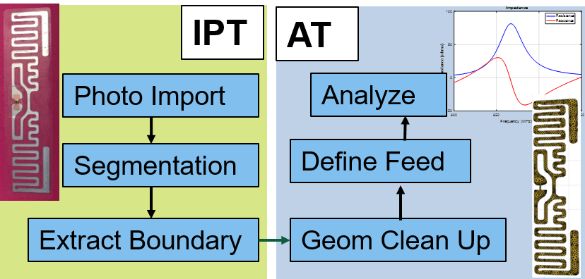
Antenna Model Generation and Full-Wave Analysis From Photo
Demonstrates the process of using a photograph of a planar antenna to generate a viable antenna model and its subsequent analysis for port, surface and field characteristics. The Image Segmenter app is used to perform segmentation on the image of an RFID tag, and the resulting boundaries are used to set up the antenna model in Antenna Toolbox™. An initial impedance analysis is done over a frequency range to understand the port characteristics of the antenna. After determining the resonant frequency, the current and far-field pattern are calculated and plotted.

Electromagnetic Analysis of Reconfigurable Intelligent Surface
Model the response of a reconfigurable intelligent surface (RIS) using full-wave electromagnetic simulation. The RIS, also known as the intelligent reflecting surface (IRS), large intelligent surface (LIS), or metasurface, has garnered significant interest in the wireless communication community. The RIS consists of a large array of subwavelength unit cell elements which can manipulate the phase, amplitude, polarization, or frequency of the incident signal. If an obstacle blocks the direct path between the base station (BS) and the user equipment (UE), the parasitic reflection of the RIS can provide an alternative path for signal transmission, as this figure shows. An external phase control mechanism can be integrated to control the reflection characteristics of the RIS.

Direction of Arrival Determination Using Full-Wave Electromagnetic Analysis
This example shows how to determine the Direction of Arrival (DoA) when the transmission source is an antenna located in the far-field region or by assuming that the incident signal behaves like a plane wave incident on the receive array. DoA can be denoted by two angles phi and theta in the spherical co-ordinate system. It is a common practice to use a receive antenna array to scan for any incoming signals and to calculate its angles of arrival with respect to the center of the array. The incoming signal is commonly assumed to arrive from a far-field transmission source. Proper accounting of receive array’s electromagnetic behavior is one of the key elements in determining the angles of arrival of the incident signal.

Field Analysis of Monopole Antenna
Conduct the field analysis of monopole antenna using pattern function.

Analysis of Electrically Large Structures Using Hybrid MoM and FMM
Analyze electrically large antennas using two solvers in Antenna Toolbox™: the hybrid method of moments (MOM) and the fast multipole method (FMM). The overall size of an antenna can be expressed in electrical terms, as a function of the frequency of operation or wavelength λ. Doing so can enable you to choose the electromagnetic solver to deploy for analysis.
Analyze Cylindrical Reflector Antenna with Horn Array Feed
Analyze an antenna consisting of a cylindrical reflector with a linear array of horns.

Verification of Far-Field Array Pattern Using Superposition with Embedded Element Patterns
The far-field radiation pattern of a fully excited array can be recreated from the superposition of the individual embedded patterns of each element. The pattern multiplication theorem in array theory states that the far-field radiation pattern of an array is the product of the individual element pattern and the array factor. In the presence of mutual coupling, the individual element patterns are not identical and therefore invalidates the result from pattern multiplication. However, by computing the embedded pattern for each element and using superposition, we can show the equivalence to the array pattern under full excitation.

Subarrays in Large Finite Array for Hybrid Beamforming
Design subarrays in large finite array for hybrid beam forming. Hybrid beamforming combines analog beamforming with digital precoding to intelligently form the patterns transmitted from a large antenna array.

FMCW Patch Antenna Array
Describes the modeling of a 77 GHz 2-by-4 antenna array for Frequency-Modulated Continuous-Wave (FMCW) applications. The presence of antennas and antenna arrays in and around vehicles has become a commonplace with the introduction of wireless collision detection, collision avoidance, and lane departure warning systems. The two frequency bands considered for such systems are centered around 24 GHz and 77 GHz, respectively. In this example, we will investigate the microstrip patch antenna as a phased array radiator. The dielectric substrate is air.