Hamming Encoder
Create Hamming code from binary vector data
Libraries:
Communications Toolbox /
Error Detection and Correction /
Block
Description
The Hamming Encoder block creates a Hamming code with message length K and codeword length N. For more information, see Hamming Coding.
Examples
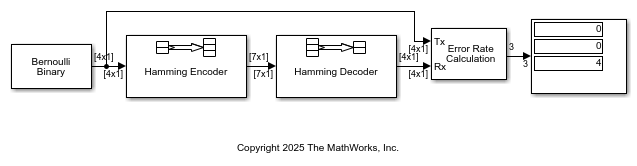
This example shows how to model a simple encoder and decoder using appropriate vector lengths for the code and message.
The cm_hamming model includes these blocks:
Bernoulli Binary Generator block with
Samples per frameset to4to match the Hamming encoder message lengthHamming Encoder block with default parameter values
Hamming Decoder block with default parameter values
Error Rate Calculation block with
Output dataset toPortDisplay block connected to the output port of the Error Rate Calculation block
To display the vector length of signals in the model, go to Debug > Diagnostics > Information Overlays > Signals and select Signal Dimensions. The connector lines show the signal attributes. To compile the model, press Ctrl+D. Run the model to display the error rate statistics.
This example shows how to adjust the Eb/N0 setting for the AWGN channel to account for the coding rate when your simulation uses coding.
The slex_hamming_check.slx model performs forward error correction (FEC) coding on a BPSK-modulated signal that gets filtered through an AWGN channel. The model uses BPSK Modulator Baseband, AWGN Channel, and BPSK Demodulator Baseband discrete blocks to simulate a binary symmetric channel. To account for difference between the coded and uncoded Eb/N0, the AWGN channel block computes the coded Eb/N0 as Eb/N0 + 10log10(K/N) dB, where K/N is the code rate and Eb/N0 is the uncoded Eb/N0. The Hamming Encoder block has an input bit period of 1 second and the output bit period decreases, by a factor of the K/N code rate, to 4/7 seconds. Due to the coding rate, the Binary Symmetric Channel has a bit period of 4/7 seconds.
The model initializes variables used to configure block parameters by using the PreLoadFcn callback function. For more information, see Model Callbacks (Simulink).
model = 'slex_hamming_check';
open_system(model);

The AWGN channel block must also configure the Number of bits per symbol and Input signal power, referenced to 1 ohm (watts) parameter settings based on the modulated signal. This example uses BPSK modulation, so the AWGN Channel block has the number of bits per symbol set to 1. The model includes a Power Meter block that measures the signal power at the AWGN input to confirm the setting required for the input signal power of the AWGN Channel block.
To compare simulation with theory, produce error rate results and a plot. The theoretical channel error probability for the coded signal is Q(sqrt(2*Ebc/N0)), where Q() is the standard Q function and Ebc/N0 is the coded Eb/N0 in linear units (not in dB). Compute the theoretical BER upper limit bound of a linear, rate 4/7 block code with a minimum distance of 3, and hard decision decoding for a BPSK-modulated signal in AWGN over a range of Eb/N0 values by using the bercodingslex_hamming_check model over the same range of Eb/N0 values.
EbNoVec = 0:2:10;
theorBER = bercoding(EbNoVec,'block','hard',7,4,3);

berVecBSC  = zeros(length(EbNoVec),3);
for n   = 1:length(EbNoVec)
    EbNo = EbNoVec(n);
    sim(model);
    berVecBSC(n,:) = berBSC(end,1);
end
Plot the results by using the semilogy function to show the nearly identical results. The model has the Error Rate Calculation block configured to run each Eb/N0 point until 200 errors occur or the block receives 10^6 bits.
semilogy( ...
    EbNoVec,berVecBSC(:,1),'d', ...
    EbNoVec,theorBER,'-');
legend('BSC BER','Theoretical BER', ...
    Location="southwest");
xlabel("Eb/N0 (dB)");
ylabel("Error Probability");
title("Bit Error Probability");
grid on;

Ports
Input
Output
Parameters
Block Characteristics
Data Types |
|
Multidimensional Signals |
|
Variable-Size Signals |
|
More About
Extended Capabilities
Version History
Introduced before R2006a