SSB AM Modulator Passband
Modulate using single-sideband amplitude modulation
Libraries:
Communications Toolbox /
Modulation /
Analog Passband Modulation
Description
The SSB AM Modulator Passband block modulates a signal using single-sideband amplitude modulation with a Hilbert transform filter. Both the input and output signals are real scalar signals.
Examples
Sample a 100 Hz input signal at 8000 samples per second. Modulate the input signal using the single-sideband amplitude modulation method with a Hilbert transform filter of order 100. Demodulate the signal. Plot the input signal, the modulated signal, and the demodulated signal.
The ssb_response model modulates a signal using single-sideband amplitude modulation with a Hilbert transform filter and a carrier frequency of 2000 Hz and then demodulates the signal. When the model runs, it plots the signals. The model samples a 100 Hz linear frequency sweep chirp with a 400 Hz target frequency at 8000 samples per second. This configuration ensures the Hilbert transform filter operates in the flat section of the magnitude response and that the modulated signal has the desired magnitude and form.
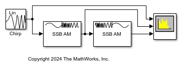
Run the model with the SSB AM Modulator Passband block configured to modulate the upper sideband. Plot the input signal, the modulated upper sideband, and the demodulated signal by using a spectrum analyzer.
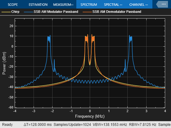
Reconfigure the SSB AM Modulator Passband block to modulate the lower sideband and plot the signals again.
Limitations
This block does not work inside a triggered subsystem.
Ports
Input
Output
Parameters
Block Characteristics
Data Types |
|
Multidimensional Signals |
|
Variable-Size Signals |
|
Algorithms
The SSB AM Modulator Passband block transmits either the lower or upper sideband signal, but not both. To control which sideband it transmits, use the Sideband to modulate parameter.
For an input signal u(t), as a function of time t, the output is
where:
fc represents the Carrier frequency (Hz) parameter.
θ represents the Initial phase (rad) parameter.
û(t) is the Hilbert transform of the input u(t).
The minus sign indicates the upper sideband and the plus sign indicates the lower sideband.
To design the Hilbert transform filter, this block uses the Analytic Signal block, which computes the complex analytic signal corresponding to each channel of the real M-by-N input, u
where and denotes the Hilbert transform. The real part of the output in each channel is a replica of the real input in that channel. The imaginary part is the Hilbert transform of the input. In the frequency domain, the analytic signal retains the positive frequency content of the original signal while zeroing-out negative frequencies and doubling the DC component.
The block computes the Hilbert transform using an equiripple FIR filter with the order that you specify using the Hilbert Transform filter order (must be even) parameter, n. This linear phase filter uses the Remez exchange algorithm and imposes a delay of n/2 on the input samples.
Because the block uses this filter, it requires a carrier frequency that exceeds the sample rate of the input signal by at least 10%.
For example, this plot shows the response for a 10 Hz input signal at 8000 samples per second passed through a Hilbert transform filter of order 100.
A carrier frequency that is 10% to 90% higher than the sample rate of the input signal, ensures that the Hilbert transform filter operates in the flat section of its magnitude response (shown in blue) and that the modulated signal has the desired magnitude and form.
References
[1] Peebles, Peyton Z, Jr. Communication System Principles. Reading, MA: Addison-Wesley, 1976.
Extended Capabilities
Version History
Introduced before R2006a