Frequency Modulation
Frequency modulation (FM) is a baseband modulation technique in which the message modulates the frequency of a constant amplitude signal. The transmitted signal is created by switching the carrier frequency at data transitions. At the receiver, the modulated signal can be coherently separated (demodulated) because of the frequency difference. FM can be regarded as a special case of phase modulation.
Communications Toolbox™ software includes these modulation and demodulation functions, System objects, and blocks to model frequency shift keying (FSK) modulation.
| Functions | System objects | Blocks |
|---|---|---|
FSK
FSK is a special case of orthogonal signals that differ in frequency.
As described in Proakis ([2]), the signal waveforms may be expressed as
Frequency Modulation Examples
These examples demonstrate FM modulation techniques.
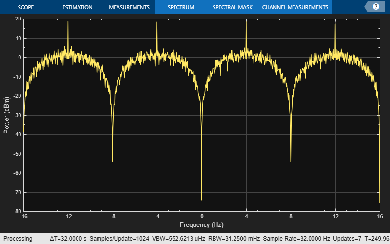
Plot FSK Signal Spectrum
Generate an FSK modulated signal and display its spectral characteristics.
Set the function parameters.
M = 4;       % Modulation order
freqsep = 8; % Frequency separation (Hz)
nsamp = 8;   % Number of samples per symbol
Fs = 32;     % Sample rate (Hz)
Generate random M-ary symbols.
x = randi([0 M-1],1000,1);
Apply FSK modulation.
y = fskmod(x,M,freqsep,nsamp,Fs);
Create a spectrum analyzer System object™ and call it to display a plot of the signal spectrum.
specAnal = spectrumAnalyzer(SampleRate=Fs);
specAnal(y)
Apply FSK Modulation in Various Fading Channels
Pass an FSK signal through a Rayleigh multipath fading channel. Change the signal bandwidth to observe the impact of the fading channel on the FSK spectrum.
Flat Fading Channel
Set modulation order to 4, the modulated symbol rate to 45 bps, and the frequency separation to 200 Hz.
M = 4;           % Modulation order
symbolRate = 45; % Symbol rate (bps)
freqSep = 200;   % Frequency separation (Hz)
Calculate the samples per symbol parameter, sampPerSym, as a function of the modulation order, frequency separation, and symbol rate. To avoid output signal aliasing, the product of sampPerSym and symbolRate must be greater than the product of M and freqSep. Calculate the sample rate of the FSK output signal.
sampPerSym = ceil(M*freqSep/symbolRate);
fsamp = sampPerSym*symbolRate;
Create an FSK modulator.
fskMod = comm.FSKModulator(M, ...
    FrequencySeparation=freqSep, ...
    SamplesPerSymbol=sampPerSym, ...
    SymbolRate=symbolRate);
Set the path delays and average path gains for the three-path fading channel.
pathDelays = [0 3 10]*1e-6; % Discrete delays (s)
avgPathGains = [0 -3 -6];   % Average path gains (dB)
By convention, the delay of the first path is typically set to zero. For subsequent paths, a 1 microsecond delay corresponds to a 300 m difference in path length. The path delays and path gains specify the average delay profile of the channel.
Create a Rayleigh channel using the defined parameters. Set the Visualization property to display the impulse and frequency responses.
channel = comm.RayleighChannel( ...
    SampleRate=fsamp, ...
    PathDelays=pathDelays, ...
    AveragePathGains=avgPathGains, ...
    MaximumDopplerShift=0.01, ...
    Visualization='Impulse and frequency responses', ...
    SamplesToDisplay='10%');
Generate random data symbols and apply FSK modulation.
data = randi([0 3],2000,1);
modSig = fskMod(data);
Create a spectrum analyzer object to plot the FSK modulated signal and the received signal after flat fading channel filtering.
sa1 = spectrumAnalyzer( ...
    SampleRate=fsamp, ...
    ChannelNames=["FSK modulated signal", ...
        "Flat fading channel"]);
The modulated signal is composed of four tones, each having approximately 20 dBm peak power separated by 200 Hz.
Pass the signal through the Rayleigh fading channel and apply AWGN having a 25 dB signal-to-noise ratio.
snrdB = 25;
raylFadedData = channel(modSig);


rxSig = awgn(raylFadedData,snrdB);
The impulse and frequency responses show that the channel behaves as though it were flat. This flat response is because the signal bandwidth, 800 Hz, is much smaller than the coherence bandwidth, 50 kHz.
Plot the signal spectrum of the FSK-modulated signal before and after channel filtering. The four tones comprising the FSK signal maintain the same frequency separation and peak power levels relative to each other. The absolute peak power levels have decreased due to the fading channel.
sa1(modSig,rxSig)
release(sa1)

Frequency-Selective Fading
Increase the symbol rate to 45 kbps and the frequency separation to 200 kHz. Calculate the new samples per symbol and sample rate parameters. Release the FSK modulator object and update its configuration.
symbolRate = 45e3;
freqSep = 200e3;

release(fskMod)
fskMod.SymbolRate = symbolRate;
fskMod.FrequencySeparation = freqSep;
Create a spectrum analyzer object to plot the FSK modulated signal and the received signal after frequency-selective fading channel filtering.
sampPerSym = ceil(M*freqSep/symbolRate);
sa2 = spectrumAnalyzer( ...
    SampleRate=sampPerSym*symbolRate, ...
    ChannelNames=["FSK modulated signal", ...
        "Frequecy-selective fading channel"]);
Apply FSK modulation to the transmission data.
modSig = fskMod(data);
Release the channel object and update the channel sample rate property. Pass the signal through the Rayleigh fading channel and apply AWGN. The impulse and frequency responses show that the multipath fading is frequency selective.
release(channel)
fsamp = sampPerSym*symbolRate;
channel.SampleRate = fsamp;

rxSig = awgn(channel(modSig),25);


Plot the signal spectrum of the FSK-modulated signal before and after channel filtering. The spectrum has the same shape as in the flat-fading case, but the four tones are now separated by 200 kHz. There are still four identifiable tones, but their relative peak power levels differ due to the frequency-selective fading. The 800 kHz signal bandwidth is larger than the 50 kHz coherence bandwidth.
sa2(modSig,rxSig)
release(sa2)

References
[1] Sklar, Bernard. Digital Communications: Fundamentals and Applications. 2nd ed. Upper Saddle River, NJ: Prentice-Hall PTR, 2001.
[2] Proakis, John G. Digital Communications. 5th ed. New York: McGraw Hill, 2007.
See Also
Functions
rcosdesign|fskmod|fskdemod
Objects
comm.RaisedCosineTransmitFilter|comm.RaisedCosineReceiveFilter|comm.FSKModulator|comm.FSKDemodulator
Blocks
- Raised Cosine Transmit Filter | Raised Cosine Receive Filter | M-FSK Modulator Baseband | M-FSK Demodulator Baseband