Main Content

M-FSK Demodulator Baseband

Demodulate FSK-modulated data

Library

FM, in Digital Baseband sublibrary of Modulation

  • M-FSK Demodulator Baseband block

Description

The M-FSK Demodulator Baseband block demodulates a signal that was modulated using the M-ary frequency shift keying method. The input is a baseband representation of the modulated signal. The input and output for this block are discrete-time signals. This block accepts a scalar value or column vector input signal of type single or double. For information about the data types each block port supports, see Supported Data Types.

The M-ary number parameter, M, is the number of frequencies in the modulated signal. The Frequency separation parameter is the distance, in Hz, between successive frequencies of the modulated signal.

The M-FSK Demodulator Baseband block implements a non-coherent energy detector. To obtain the same BER performance as that of coherent FSK demodulation, use the CPFSK Demodulator Baseband block.

Integer-Valued Signals and Binary-Valued Signals

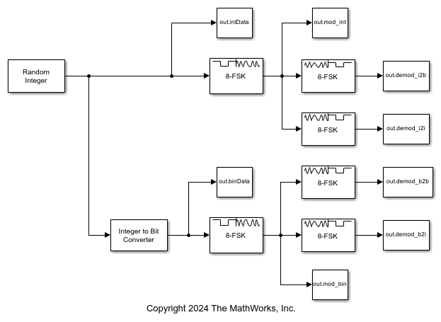
When you set the Output type parameter to Integer, the block outputs integer values in the range [0, (M1)]. M represents the M-ary number block parameter.

When you set the Output type parameter to Bit, the block outputs binary-valued signals that represent integers. The block represents each integer using a group of K = log2(M) bits, where K represents the number of bits per symbol. The output vector length must be an integer multiple of K.

The Symbol set ordering parameter indicates how the block maps a symbol to a group of K output bits. When you set the parameter to Binary, the block maps the integer, I, to [u(1) u(2) ... u(K)] bits, where the individual u(i) are given by

I=i=1Ku(i)2Ki

u(1) is the most significant bit.

For example, if M = 8, you set Symbol set ordering to Binary, and the demodulated integer symbol value is 6, then the binary output word is [1 1 0].

When you set Symbol set ordering to Gray, the block assigns bit outputs from points of a predefined Gray-coded signal constellation. The predefined M-ary Gray-coded signal constellation assigns the bit representation in the pth row of bit matrix b to the pth integer, where the left-most bit is the most significant bit (MSB).

M = 8; P = [0:M-1]';
nBits = log2(M);
b = int2bit(bitxor(P,floor(P/2)),nBits);
b = reshape(b,[],8)';

The typical Binary to Gray mapping for M = 8 is shown in the following tables.

Binary to Gray Mapping for Bits

Binary CodeGray Code
000000
001001
010011
011010
100110
101111
110101
111100

Binary to Gray Mapping for Integers

Binary CodeGray Code
00
11
23
32
46
57
65
74

Whether the output is an integer or a binary representation of an integer, the block maps the highest frequency to the integer 0 and maps the lowest frequency to the integer M-1. In baseband simulation, the lowest frequency is the negative frequency with the largest absolute value.

Single-Rate Processing

In single-rate processing mode, the input and output signals have the same port sample time. The block implicitly implements the rate change by making a size change at the output when compared to the input. The input width must be an integer multiple of the Samples per symbol parameter value, and the input can be a column vector.

  • When you set Output type to Bit, the output width is K times the number of input symbols and the M-ary number value must be a power of two.

  • When you set Output type to Integer, the output width is the number of input symbols.

Multirate Processing

In multirate processing mode, the input and output signals have different port sample times. The input must be a scalar. The output symbol time is the product of the input sample time and the Samples per symbol parameter value.

  • When you set Output type to Bit, the output width equals the number of bits per symbol and the M-ary number value must be a power of two.

  • When you set Output type to Integer, the output is a scalar.

To run the M-FSK Demodulator block in multirate mode, clear the Treat each discrete rate as a separate task checkbox (in Simulation > Configuration Parameters > Solver).

Parameters

M-ary number

Number of frequencies in the modulated signal, specified as a positive integer ≥ 2.

Output type

Determines whether the output consists of integers or groups of bits. If this parameter is set to Bit, then the M-ary number parameter must be a power of two.

Symbol set ordering

Determines how the block maps each integer to a group of output bits.

Note

When you set Symbol set ordering to Gray, the M-ary number value must be a power of two.

Frequency separation (Hz)

The distance between successive frequencies in the modulated signal.

Samples per symbol

The number of input samples that represent each modulated symbol.

Rate options

Select the rate processing method for the block.

  • Enforce single-rate processing — When you select this option, the input and output signals have the same port sample times. The block implements the rate change by making a size change at the output when compared to the input. The output width is the number of symbols (which is given by dividing the input length by the Samples per symbol parameter value when the Output type parameter is set to Integer).

  • Allow multirate processing — When you select this option, the input and output signals have different port sample times. The output period is the same as the symbol period and equals the product of the input period and the Samples per symbol parameter value.

For more information, see Single-Rate Processing and Multirate Processing in the Description section of this page.

Output data type

The output type of the block can be specified here as boolean, int8, uint8, int16, uint16, int32, uint32, or double. By default, the block sets this to double.

Supported Data Types

PortSupported Data Types

Input

  • Double-precision floating point

  • Single-precision floating point

Output

  • Double-precision floating point

  • Boolean

  • 8-, 16-, and 32-bit signed integers

  • 8-, 16-, and 32-bit unsigned integers

References

[1] Sklar, Bernard. Digital Communications: Fundamentals and Applications. Upper Saddle River, NJ: Prentice-Hall, 2001.

Extended Capabilities

C/C++ Code Generation
Generate C and C++ code using Simulink® Coder™.

Version History

Introduced before R2006a

Go to top of page