Symbol Mapping Examples
Compare Error Rate for Gray- and Binary-Coded Ordering
Compare Gray coding with binary coding by using PSK modulation. This simulation iterates over a range of bit energy to noise power spectral density, , values and runs until either the specified maximum number of bit errors (maxNumErrs) or the maximum number of bits (maxNumBits) is reached for Gray coding for each point.
Initialization
Initialize the system variables and set the random number generator seed to ensure repeatable results. The state of the random number generator is stored before setting the random stream seed, and restored at the end of the example.
M = 8;          % Modulation order for 8-PSK
spf = 10000;    % Samples per frame
maxNumErrs=100; % Stop simulation if 100 errors reached
maxNumBits=1e8; % Stop simulation if 1e8 bits transmitted

prevState = rng(529558);
Create symbol error rate and bit error rate calculator System objects to compare the demodulated integer and bit data with the original source data. This comparison yields symbol error and bit error statistics. The output of the error rate calculator System object is a three-element vector containing the calculated error rate, the number of errors observed, and the amount of data processed. The simulation uses the three-element vector to determine when to stop the simulation.
symerrorg = comm.ErrorRate;
biterrorg = comm.ErrorRate;
biterrorb = comm.ErrorRate;
Frame Processing Loop
Configure a frame processing loop where data is coded, modulated, and demodulated using 8-PSK modulation mapped to Gray- and binary-coded constellations. The loop simulates the communications system for values in the range 0 dB to 12 dB in steps of 2 dB. The convertSNR function converts values to SNR for the processing loop.
For each value, the simulation stops when either the maximum number of errors (maxNumErrs) or the maximum number of bits (maxNumBits) processed by the bit error rate calculator System object is reached for the Gray coded bits.
EbNoVec = 0:2:12; % Eb/No values to simulate
snrVec = convertSNR(EbNoVec,"ebno","snr",BitsPerSymbol=log2(M));
SERVec = zeros(size(EbNoVec)); % SER history for Gray ordered
BERVecg = zeros(size(EbNoVec)); % BER history for Gray ordered
BERVecb = zeros(size(EbNoVec)); % BER history for binary ordered
for p = 1:length(EbNoVec)
  % Reset System objects
  reset(symerrorg);
  reset(biterrorg);
  reset(biterrorb);
  % Reset SER and BER for the current Eb/No value
  SER = zeros(3,1);
  BERg = zeros(3,1);
  BERb = zeros(3,1);
  while (BERg(2)<maxNumErrs) && (BERg(3)<maxNumBits)
    % Generate random data
    txSym = randi([0 M-1],spf,1,"uint8");
    txBits = int2bit(txSym,log2(M),true); % Convert symbols to bits
    txg = pskmod(txBits,M,0,"gray",InputType="bit");
    txb = pskmod(txBits,M,0,"bin",InputType="bit");
    rxg = awgn(txg,snrVec(p));
    rxb = awgn(txb,snrVec(p));
    rxBitsg = pskdemod(rxg,M,0,"gray", ...
        OutputType="bit",OutputDataType="uint8");
    rxBitsb = pskdemod(rxb,M,0,"bin", ...
        OutputType="bit",OutputDataType="uint8");
    rxSym = bit2int(rxBitsg,log2(M),true);
    SER = symerrorg(txSym,rxSym); % SER for Gray-coded data
    BERg = biterrorg(txBits,rxBitsg); % BER for Gray-coded data
    BERb = biterrorb(txBits,rxBitsb); % BER for binary-coded data
  end
  % Save history of SER and BER values
  SERVec(p) = SER(1);
  BERVecg(p) = BERg(1);
  BERVecb(p) = BERb(1);
end
Restore the default stream.
rng(prevState)
Results Analysis
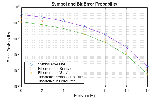
Analyze the data from the example and compare theoretical performance with simulation performance. Calculate theoretical error probabilities by using the berawgn function. Plot the simulated symbol error rate, bit error rate for Gray and binary coding, and the theoretical symbol error and bit error probabilities for Gray coding.
[theorBER,theorSER] = berawgn(EbNoVec,"psk",M,"nondiff");

figure;
semilogy( ...
    EbNoVec,SERVec,"o", ...
    EbNoVec,BERVecb,"x", ...
    EbNoVec,BERVecg,"*", ...
    EbNoVec,theorSER,"-", ...
    EbNoVec,theorBER,"-");
legend("Symbol error rate", "Bit error rate (Binary)", ...
    "Bit error rate (Gray)", "Theoretical symbol error rate", ...
    "Theoretical bit error rate", "Location","SouthWest");
xlabel("Eb/No (dB)");
ylabel("Error Probability");
title("Symbol and Bit Error Probability");
grid on;
Gray-Coded M-PSK Modulation Error Rate in AWGN Channel Using Simulink
This example uses the doc_gray_code to compute bit error rates (BER) and symbol error rates (SER) for M-PSK modulation. The theoretical error rate performance of M-PSK modulation in AWGN is compared to the error rate performance for Gray-coded symbol mapping and to the error rate performance of binary-coded symbol mapping.

The Random Integer Generator block serves as the source, producing a sequence of integers. The Integer to Bit Converter block converts each integer into a corresponding binary representation. The M-PSK Modulator Baseband block in the doc_gray_code model:
Accepts binary-valued inputs that represent integers in the range [0, (M - 1], where M is the modulation order.
Maps binary representations to constellation points using a Gray-coded ordering.
Produces unit-magnitude complex phasor outputs, with evenly spaced phases in the range [0, (2
 (M - 1) / M)].
The AWGN Channel block adds white Gaussian noise to the modulated data. The M-PSK Demodulator Baseband block demodulates the noisy data. The Bit to Integer Converter block converts each binary representation to a corresponding integer. Then two separate Error Rate Calculation blocks calculate the error rates of the demodulated data. The block labeled SER Calculation compares the integer data to compute the symbol error rate statistics and the block labeled BER Calculation compares the bits data to compute the bit error rate statistics. The output of the Error Rate Calculation block is a three-element vector containing the calculated error rate, the number of errors observed, and the amount of data processed.
To reduce simulation run time and ensure that the statistics of the errors remain stable as the Eb/N0 ratio increases, the model is configured to run until 100 errors occur or until 1e8 bits have been transmitted.
The model initializes variables used to configure block parameters by using the PreLoadFcn callback function. For more information, see Model Callbacks (Simulink).
Produce Error Rate Curves
Compute the theoretical BER for nondifferential 8-PSK in AWGN over a range of Eb/N0 values by using the berawgndoc_gray_code model with Gray-coded symbol mapping over the same range of Eb/N0 values.
Compare Gray coding with binary coding, by modifying the M-PSK Modulator Baseband and M-PSK Demodulator Baseband blocks to set the Constellation ordering parameter to Binary instead of Gray. Simulate the doc_gray_code model with binary-coded symbol mapping over the same range of Eb/N0 values.
Plot the results by using the semilogy function. The Gray-coded system achieves better error rate performance than the binary-coded system. Further, the Gray-coded error rate aligns with the theoretical error rate statistics.

Gray Encode Modulated Signal
For the PSK, DPSK, FSK, QAM, and PAM modulation types, Gray constellations are obtained by setting the symbol mapping to Gray-encoding in the corresponding modulation function, System object™, or block. The default symbol order uses Gray-encoded ordering for modulation.
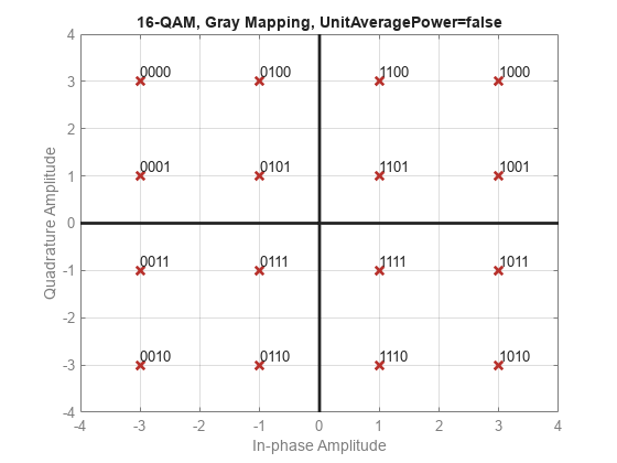
For modulation functions, you can specify "gray", "bin", or a vector specifying custom symbol ordering. This example uses the qammod function with Gray-encoded symbol mapping. Check the constellation plot, the modulated symbols are Gray-encoded because all adjacent elements differ by only one bit.
k = 4;
M = 2^k;
y = int2bit([0:M-1]',k,false);
symorder = "gray";
xmap = qammod(y,M,symorder, ...
    InputType="bit", ...
    PlotConstellation=true);