Generate HDL Code for Two-Speed Transmission Model Containing Mode Charts
This example shows how to generate HDL code for a Simscape™ model containing mode charts.
Simscape Models with Mode Charts
You can use a mode chart implementation to model a Simscape component with multiple operating modes and transitions. Mode charts provide an intuitive way to model components characterized by a discrete set of distinct operating modes. A car clutch is a good example of such a component. To learn more about mode charts, see modecharts (Simscape) and Mode Chart Modeling (Simscape).
In this example, a two-speed transmission model with braking is designed for HDL code generation. This model uses the Partitioning solver as a local solver. For more information, see Understanding How the Partitioning Solver Works (Simscape). First, you generate an HDL implementation model by using the Simscape HDL Workflow Advisor. For this implementation model, you generate the HDL code and can synthesize the results by using the guided steps in the HDL Workflow Advisor.
Set Up Synthesis Tool Path
If you want to synthesize the generated HDL code, before you use HDL Coder™ to generate code, set up your synthesis tool path. For example, if your synthesis tool is Xilinx® Vivado®, install the latest version of Xilinx Vivado as listed in HDL Language Support and Supported Third-Party Tools and Hardware.
Then, set the tool path to the installed Xilinx Vivado executable by using the hdlsetuptoolpath function:
hdlsetuptoolpath('ToolName','Xilinx Vivado','ToolPath','C:\Xilinx\Vivado\2020.2\bin\vivado.bat')
Two-Speed Transmission Model with Braking
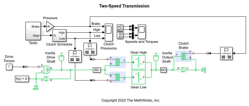
The two-speed transmission model is a Simscape driveline model. This transmission model couples the gears in a simple way, with each gear and the brake associated with its own clutch. Coupling one gear requires engaging and locking the corresponding clutch, while ensuring that the other two clutches are disengaged. The brake clutch is directly activated by its own switch. Two clutches control which gear is selected. A brake is connected to the output shaft and can be controlled independently. The highlighted blocks in the model contain mode charts.
Open the model from the MATLAB® command prompt.
ModelName = 'sdl_transmission_2spd_hdl';
open_system(ModelName)

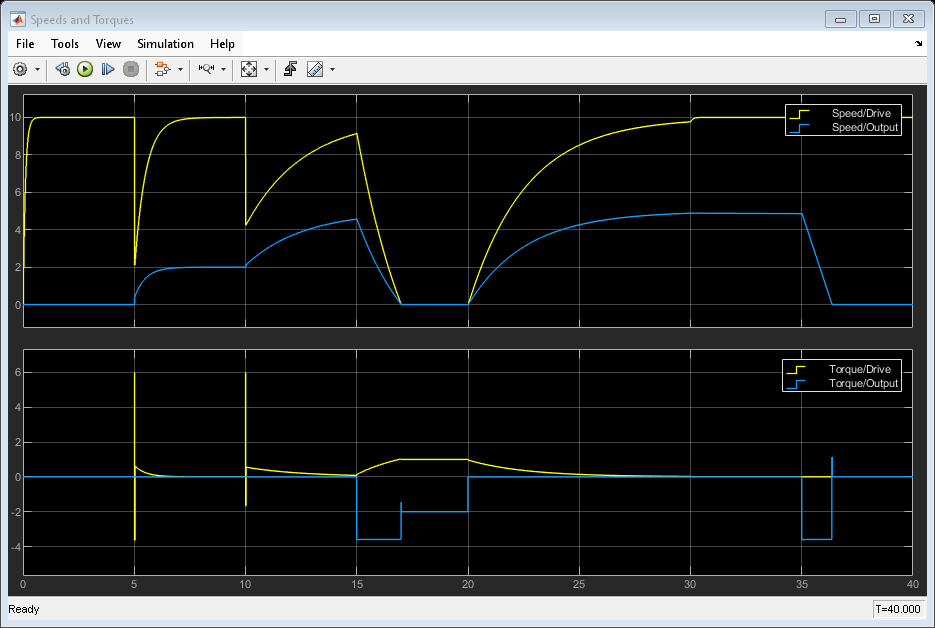
To see how the model works, simulate it
sim(ModelName)
open_system(['sdl_transmission_2spd_hdl' '/Speeds and Torques'])

Generate HDL Implementation Model
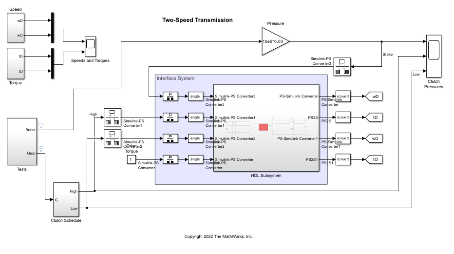
The Simscape HDL Workflow Advisor converts the Simscape plant model to an HDL-compatible implementation model from which you generate HDL code. To generate the HDL implementation model:
1. Open the Simscape HDL Workflow Advisor.
sschdladvisor('sdl_transmission_2spd_hdl')
2. In the Implementation model generation task drop-down list, right-click the Generate implementation model task, then select Run to Selected Task from the list. To get better resource utilization, in the Generate implementation model task window, set Map state space parameter to RAM to On.
After the task passes, you see a link to the HDL implementation model gmStateSpaceHDL_sdl_transmission_2spd_hdl.

Generate HDL Code
To modify the configuration parameter values for HDL code generation, run
hdlsetup('gmStateSpaceHDL_sdl_transmission_2spd_hdl')
HDL Workflow Advisor
The HDL Workflow Advisor guides you through the necessary tasks required for generating HDL code and an FPGA design process. It provides you with feedback on the results of each task. When you complete the tasks, you have a synthesis result report from one of the supported synthesis tools.
To open the subsystem HDL Subsystem within the HDL implementation model into the HDL Workflow Advisor, run
hdladvisor('gmStateSpaceHDL_sdl_transmission_2spd_hdl/HDL Subsystem')
You can also open the HDL Workflow Advisor from your model window. Right-click the HDL Subsystem and select HDL Workflow Advisor from the list.
Set Target Device and Synthesis Tool
Before you generate HDL code, if you want to deploy the code onto a target platform, specify the synthesis tool.
Open the HDL Workflow Advisor.
Under the Set Target task folder, in the Set Target Device and Synthesis Tool task, specify Target workflow as
Generic ASIC/FPGAand Synthesis tool asXilinx Vivado. The rest of the fields are auto-populated. Specify the Family asKintex7, Device asxc7k325t, Package asfbg676, and Speed as -1.In the Set Target Frequency window, specify the Target Frequency as 100.
Select the task that you want to run and click Run This Task.
HDL Code Generation
In the HDL Code Generation task folder, click Set HDL Options and then click the HDL Code Generation Settings button. This opens the Configuration Parameters dialog box. Select
Adaptive pipeliningunder HDL Code Generation > Optimizations > Pipelining and click Apply.Under the HDL Code Generation > Global Settings > Clock Settings section, set the
Oversampling factorto 500. Click Apply then click OK. To generate HDL code, run the tasks under the HDL Code Generation task folder.
Synthesize Generated HDL Code
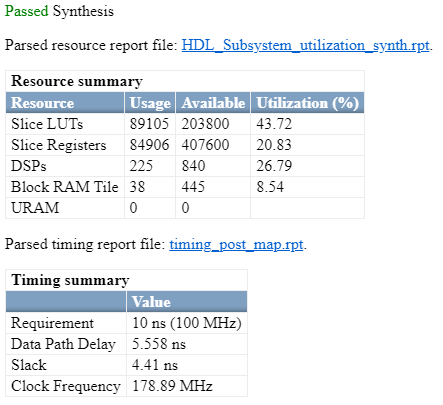
HDL Coder synthesizes the HDL code on the target platform and generates area and timing reports for your design based on the target device that you specify. You can run logic synthesis for a specified FPGA device and get the synthesis reports.
In the FPGA Synthesis and Analysis task folder:
Create an FPGA synthesis project for your supported FPGA synthesis tool.
Start supported FPGA synthesis tools to perform synthesis, mapping, and place/route tasks. To run FPGA synthesis, right-click the Run Synthesis task under the Perform Synthesis and P/R subtask folder. This starts Xilinx Vivado and executes the Vivado Synthesis step. You can annotate your original model with critical path information obtained from the synthesis tools.

See Also
Functions
Topics
- Generate HDL Code for Simscape Models
modecharts(Simscape)- Mode Chart Modeling (Simscape)
- Hardware-in-the-Loop Implementation of Simscape Model on Speedgoat FPGA I/O Modules
- Deploy Simscape Grid Tied Converter Model to Speedgoat IO Module Using HDL Workflow Script
- Generate HDL Code for Nonlinear Simscape Models by Using Partitioning Solver