Troubleshooting Real-Time Hardware Deployment Issues in Simscape Hardware-in-the-Loop Workflow
Simscape™ lets you rapidly create models of physical systems within the Simulink® environment. You model and simulate multidomain physical systems such as electric motors, bridge rectifiers, hydraulic actuators, and refrigeration systems by assembling fundamental components into a schematic. For more information, see How Simscape Models Represent Physical Systems (Simscape).
You can generate HDL code for the plant model you develop using Simscape blocks and then deploy the generated code to platforms such as standalone FPGA boards, Speedgoat® FPGA I/O modules, and system on a chip (SoC) devices. By deploying the plant model to an FPGA board, you can accelerate the simulation of your plant model and simulate the model in real time by using hardware-in-the-loop (HIL) simulations.
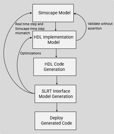
This workflow diagram shows the different stages of the Simscape HIL workflow.
In this topic, you will learn how:
Timing violations occur on hardware.
To address timing violations on hardware.
Parameter Settings
You can generate HDL code for a wide variety of Simscape networks and simulate it. However, hardware deployment of the same models has certain requirements that need to be addressed early in the design process. For instance, the generated HDL code may consume a lot of hardware resources. Understanding how your design maps to your target device, is key to generating HDL code that will meet your needs when implemented downstream.
When you generate HDL code and deploy the plant model onto an FPGA, you may want to improve the sampling frequency.
Sampling Frequency: The sampling frequency (FPGA sampling frequency) is the frequency at which the models run on the hardware. It is defined as,
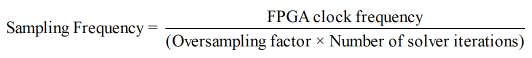
The sampling frequency depends on these parameters:
FPGA clock frequency
Oversampling factor
Number of solver iterations
The real time step on FPGA,
Ts_fpga, is the sample time at which the models run on the hardware. It is the reciprocal of the sampling frequency.The value of Simscape sample time is fixed for a Simscape model. Simscape sampling frequency is the reciprocal of the Simscape sample time. For the Simscape model simulation, you can specify the Sample time in the Solver Configuration (Simscape) block dialog box under the Use local solver parameter. To learn more about how this block is used in your model before running the Simscape HDL Workflow Advisor, see Generate and Validate HDL Code for Simscape Model.
Number of Solver Iterations: The number of solver iterations refer to the number of times the state-space model is executed per time step. The Simscape HDL Workflow Advisor calculates the number of iterations that is required for executing the state-space model, automatically. On the Solver Configuration block, you can select the Use fixed-cost runtime consistency iterations check box and specify a custom value for the number of solver iterations in Nonlinear iterations text box.
Oversampling Factor: The Oversampling factor specifies the factor by which the global clock signal is a multiple of the base rate at which the model operates. Generation of the global oversampling clock affects the generated HDL code. It does not affect the simulation behavior of your model. You can specify the value of oversampling factor in the Clock Settings section of the HDL Code Generation > Global Settings pane in the Configuration Parameters dialog box. For more information on oversampling factor, see Oversampling factor.
FPGA Clock Frequency: The FPGA clock frequency refers to the clock rate for the FPGA implementation of your design. HDL Coder™ modifies the clock module setting in the reference design to produce the clock signal with the target frequency.
The Simscape HDL Workflow Advisor calculates target frequency based on the details you specify for the Synthesis Tool. This calculation is limited to Simscape models containing a single Simscape network with a target frequency value that is within Frequency Range (MHz).
If required, you can change the target frequency by using the Target Frequency (MHz) setting in the Set Target Frequency task in the HDL Workflow Advisor. For more information, see HDL Workflow Advisor Tasks.
The Speedgoat boards that are supported by
Xilinx
                Vivado
use theIP Core Generationworkflow infrastructure. Enter a target frequency value that is within Frequency Range (MHz). If you do not specify the target frequency, HDL Coder uses Default (MHz) target frequency.
To get correct results, the Simscape time step and real time step on the FPGA need to match.
Critical Path Estimation
You can use critical path estimation to check if the model meets the timing requirement imposed by the target frequency. A critical path is a combinational path between an input and output that has the maximum timing delay. To make the critical path timing meet the target frequency that you want your design to achieve, break the critical path by adding delays. The additional delays increase the latency and register usage on the target FPGA. Critical path estimation speeds up the design iteration process. Critical path estimation is an alternative to annotating the critical path by performing FPGA Synthesis and Analysis with the HDL Workflow Advisor. For more information, see Critical Path Estimation Without Running Synthesis.
How Sample Rate Affects the Timing on the Hardware
Variation of Sample Rate
In Simscape HIL workflow, the sample rate varies for the Simscape model, the HDL implementation model, and the Simulink Real-Time (SLRT) Interface model of the same design due to the dependency on other parameters such as oversampling factor and solver iterations.
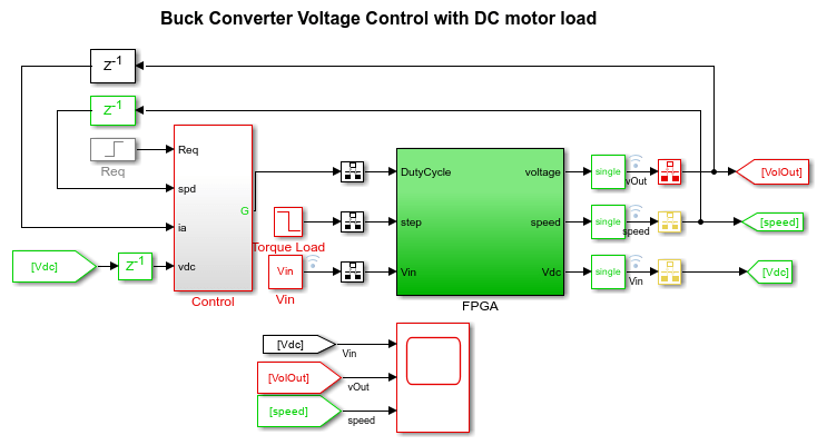
Buck Converter with DC Motor
To understand the variation of sample rate, consider the model
ee_buck_converter_dc_motor_hdl.slx that consists of a buck converter
with a DC motor as load. To see the buck converter model, run this command.
openExample('plantdeployment/DeploySimscapeDCMotorToSpeedgoatFPGAIOModuleExample',...
'supportingFile','ee_buck_converter_dc_motor_hdl.slx')
For the Simscape model, the Sample time, Ts is
6e-6, which means that the sampling frequency of the Simscape model
is 1/6 MHz. To understand the effect of different parameters on the hardware deployment,
you can change the parameter values and see the effect on the output. For example, change
the value of Ts to the default value 1e-6. On the
Modeling tab, select Model Settings > Model Properties. On the Callbacks tab, in the Model
callback pane, select PreLoadFcn and change the value of
Ts from 6e-6 to 1e-6. Save and
close the model. Reopen it for further steps.
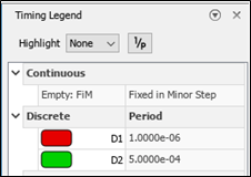
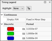
To simulate the model, click the Run button or press Ctrl + T. You can view the Timing Legend for the Simscape model. The Timing Legend contains the sample time color, annotation, and value for each sample time in the model. To view the Timing Legend:
In the Simulink model window, on the Modeling tab, click Update Model.
On the Debug tab, select Information Overlays > Timing Legend, or press Ctrl + J.
Generate the HDL implementation model by using Simscape HDL Workflow Advisor.
sschdladvisor('ee_buck_converter_dc_motor_hdl')When you generate the HDL implementation model, the Number of solver iterations is set to an optimal value of 3 by default.
The sampling frequency of the generated HDL implementation model is 1 MHz. Because the HDL Algorithm in the HDL implementation model is iterative and with the value of Number of solver iterations (3 times), the HDL Algorithm subsystem runs at an updated sampling frequency of 3 MHz. The generated HDL implementation model uses Rate Transition blocks to handle the data transfer between the two subsystems (and blocks) operating at different rates.
You can now see the updated Timing Legend for the generated HDL implementation model.
For the generated HDL implementation model, you can generate HDL code. To generate HDL code, use these commands:
open_system('gmStateSpaceHDL_ee_buck_converter_dc_motor_')
hdlsetup('gmStateSpaceHDL_ee_buck_converter_dc_motor_')
hdlset_param('gmStateSpaceHDL_ee_buck_converter_dc_motor_', 'ResourceReport', 'on')
hdlset_param('gmStateSpaceHDL_ee_buck_converter_dc_motor_', 'AdaptivePipelining', 'on');
hdlset_param('gmStateSpaceHDL_ee_buck_converter_dc_motor_', 'FloatingPointTargetConfiguration',...
hdlcoder.createFloatingPointTargetConfig('NativeFloatingPoint', 'LatencyStrategy', 'Max'));
makehdl('gmStateSpaceHDL_ee_buck_converter_dc_motor_/FPGA/HDL Subsystem');
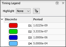
When you run this code, you may encounter an error message that says to increase the oversampling factor to 326 to provide sufficient latency budget. The adaptive pipelining optimization and maximum latency strategy used for code generation increase the required value of the oversampling factor. Update the value of oversampling factor from 275 to 326 and generate the HDL code.
hdlset_param('gmStateSpaceHDL_ee_buck_converter_dc_motor_', 'Oversampling', 326);
makehdl('gmStateSpaceHDL_ee_buck_converter_dc_motor_/FPGA/HDL Subsystem');
When you run makehdl, it generates the HDL code and the generated
model for gmStateSpaceHDL_ee_buck_converter_dc_motor_ in the
hdlsrc folder. Run the generated model
gm_gmStateSpaceHDL_ee_buck_converter_dc_motor_. Observe the Timing
Legend for this model.
To generate a Simulink Real-Time (SLRT) Interface model, follow the steps from Simulink Real-Time FPGA I/O workflow by using the HDL Workflow Advisor. To learn more about each step, see Deploy Simscape DC Motor Model to Speedgoat FPGA IO Module.
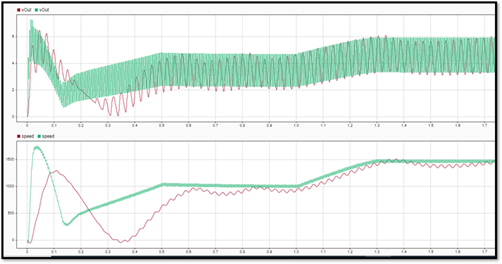
With the oversampling factor set to the value 326, the FPGA clock frequency is 3*326 MHz, or 978 MHz. However, the allowable FPGA clock frequency range for the Speedgoat devices (IO334 module) is 50-250 MHz. This creates timing violation on the hardware.
As a result, the desktop simulation and the hardware results have a mismatch due to
high FPGA clock frequency. The waveforms show the mismatch in desktop simulation (in
green) and hardware results (in red) for the outputs vOut and
speed.
How to Reduce the Sample Rate Variation
The Simscape sampling frequency is the rate at which the Simscape models run.
As mentioned in the previous section, the sampling frequency depends on FPGA clock frequency, the oversampling factor, and the number of solver iterations. To improve the sampling frequency, you can maximize the FPGA clock frequency, and minimize the oversampling factor and number of solver iterations. As you improve the sampling frequency, make sure that the updated sampling frequency is equivalent to the fixed sample time that you specify for your original Simscape model by using the Solver Configuration (Simscape) block.
You can synthesize your implementation model to find out the frequency at which the slack is positive. Then, using the number of solver iterations and the oversampling factor, calculate the correct Simscape time step.
Calculate the real time step on FPGA (Ts_fpga) by taking the
reciprocal of the FPGA sampling frequency.

The target frequency of your current design is 164 MHz for which the design meets the timing constraints. Here, the oversampling factor is 326 and the number of solver iterations is 3. The updated real time step on FPGA is
Ts_fpga = (326*3)/164 = 5.963 ≈ 6 µs
To avoid timing violations on the hardware, use the calculated value of
Ts_fpga as the Simscape sample time.
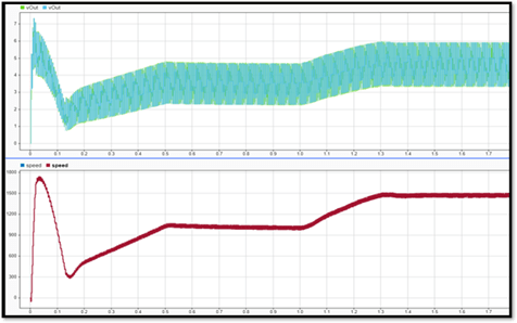
Change the sample time from 1e-6 to 6e-6 in the
PreLoadFcn callback. Save the model, close, and reopen it.
Adjusting the parameter values reduces the mismatches in the results obtained from desktop simulation and the hardware results. The desktop simulation results align closely with the hardware results.
Limitations
To estimate the correct target frequency, you need to perform model synthesis which might take some time (a few hours).
Changing the sample time affects the discretization step in the Simscape HDL Workflow Advisor. As a result, the state-space parameters (A, B, C, D parameters) change, and you need to rerun the workflow from the beginning.
See Also
Improve FPGA Sampling Frequency of HDL Implementation Model Generated from Simscape Algorithm | Validate HDL Implementation Model to Simscape Algorithm