FPGA-in-the-Loop Simulation Using MATLAB System Object
This example uses a MATLAB® System object™ and an FPGA to verify a register transfer level (RTL) design of an 8-point Fast Fourier Transform (FFT) written in VHDL®. The FFT is commonly used in digital signal processing to produce the frequency distribution of a signal.
To verify this FFT, this example includes a testbench for the System object. This testbench sends a sine wave to the HDL design under test (DUT) and plots the magnitude of the FFT output.
Set Up FPGA Design Software Environment
Before using FPGA-in-the-Loop (FIL), make sure your system environment is properly configured to access your FPGA design software. You can use the hdlsetuptoolpath function to add the FPGA design software to the system path for the current MATLAB session.
Launch FIL Wizard
Launch the FIL Wizard prepopulated with the FFT example information. The DUT is an 8-point FFT module that receives real-valued input samples with a valid signal and outputs the complex FFT result along with a data valid signal.
Enter your FPGA board information in the first step, then follow each step of the wizard to generate the FPGA programming file and the FIL System object.
filWizard('filSysObjExFILWizardInfo.mat');
Instantiate the FPGA-in-the-Loop System Object
fft8_fil is a customized hdlverifier.FILSimulation System object, which represents the HDL implementation of the FFT running on the FPGA in this simulation system.
filObj = fft8_fil;
Program FPGA
Make sure the FIL Wizard has finished generating the FPGA programming file, and check that the FPGA board is powered on and connected properly. Program the FPGA with the generated programming file.
programFPGA(filObj);
Run the Simulation
The FFT input signal consists of 100 samples of a sine wave (frequency = 40 Hz, sample rate = 320 Hz, 8-bit fixed-point). The testbench can send the input signal to the FPGA as one frame, or one sample at a time. Frame-based simulation is faster and preferred when applicable. However, sample-based simulation is necessary when there is a feedback loop between the DUT input and output.
To load the test signal, enter the following at the MATLAB command prompt:
load("filSysObjExSineWave.mat","sineWave"); % 40 Hz sine wave sampled at 320 Hz
To send the entire frame to the FPGA and observe the outputs, use the System object as a function. For example:
% Frame-based simulation
[fftReal, fftImag, fftValid] = filObj(sineWave,true(100,1));
Alternatively, you can send the data to the FPGA one sample at a time.
% Sample-based simulation
for i=1:100
    [fftReal(i), fftImag(i),fftValid(i)] = filObj(sineWave(i),true);
end
Display the Simulation Result
Since the FFT algorithm has latencies, the control signal fftValid indicates that the output data is valid. To extract the valid outputs, enter these commands in the MATLAB prompt:
fftComplex = complex(fftReal, fftImag);
fftComplex = fftComplex(fftValid == true);
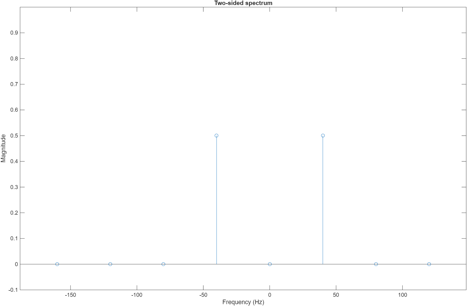
Plot the FFT magnitude on a two-sided spectrum using the first 8 samples of the FFT output. You can see the peaks at -40 Hz and 40 Hz.
N = 8; % 8-point FFT
Fs = 320; % Sample rate
stem((-N/2:N/2-1)*Fs/N, abs(fftshift(fftComplex(1:N)))/N);
xlabel('Frequency (Hz)');
ylabel('Magnitude');
title('Two-sided spectrum');
ylim([-0.1 1]);
Release the System Object
Release the FIL System object after you finish the simulation.
release(filObj);
See Also
hdlverifier.FILSimulation | FPGA-in-the-Loop Wizard