Pressure Control Solenoid
This example shows how to model, parameterize, and test a pressure control solenoid valve. This example also generates a plot of the relationship between applied solenoid force and the resulting actuator port pressure.
Model
The following figure shows the model of a pressure control solenoid valve. Here P represents the pressure source port,T represents the reservoir, and A represents the actuator port.

Pressure Control Solenoid Subsystem
This subsystem shows how the pressure control solenoid valve is modeled.

Mass Dynamics Subsystem
This subsystem shows how the spool mass dynamics are modeled, including the forces on the spool due to spool inertia; the forces on the spool due to the spring, damper, and hard stop; friction between the spool and the valve body; the change in fluid momentum at the valve entry and exit; and the pressure acting on the spool surface.

Pressure Force Subsystem
This subsystem shows how the fluid pressure at port A is modeled as a force on the spool left face.

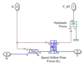
Orifice AT Subsystem
This subsystem shows how the orifice between ports A and T is modeled.

Orifice PA Subsystem
This subsystem shows how the orifice between ports A and P is modeled.

Simulation Results from Simscape Logging
This model generates a plot between the applied solenoid force and the generated actuator port pressure.

See Also
Orifice (IL) | Pipe (IL) | Spool Orifice Flow Force (IL)