Position Control of PMSM Using Quadrature Encoder
This example implements the field-oriented control (FOC) technique to control the position of a three-phase permanent magnet synchronous motor (PMSM). The FOC algorithm requires rotor position feedback, which it obtains from a quadrature encoder sensor.
You can use this example to implement position control applications by using closed-loop FOC. The example drives the motor to reach the input reference-position value. You can also configure the maximum number of rotations (in either direction) for the motor in the model initialization script.
For details about closed-loop FOC, see Field-Oriented Control and Closed-Loop Motor Control.
Model
The example includes the mcb_pmsm_PosCtrl_f28379d model.
You can use this model for both simulation and code generation.

For details about the supported hardware configuration, see the Required Hardware topic in the Generate Code and Deploy Model to Target Hardware section.
Required MathWorks Products
To simulate model:
Motor Control Blockset™
To generate code and deploy model:
Motor Control Blockset™
Embedded Coder®
C2000™ Microcontroller Blockset
Fixed-Point Designer™ (only needed for optimized code generation)
Prerequisites
1. Obtain the motor parameters. The Simulink® model uses default parameters that you can replace with values from either the motor datasheet or other sources.
However, if you have the motor control hardware, you can estimate the parameters for the motor that you want to use by using the Motor Control Blockset parameter estimation tool. For instructions, see Estimate Motor Parameters Using Motor Control Blockset Parameter Estimation Tool. The parameter estimation tool updates the motorParam variable (in the MATLAB® workspace) with the estimated motor parameters.
2. Update motor parameters. If you obtain the motor parameters from the datasheet or from other sources, update the motor and inverter parameters in the model initialization script associated with the Simulink® model. For instructions, see Estimate Control Gains and Tune Control Parameters.
If you use the parameter estimation tool, you can update the inverter parameters, but do not update the motor parameters in the model initialization script. The script automatically extracts the motor parameters from the updated motorParam workspace variable.
Simulate Model
This example supports simulation. Follow these steps to simulate the model.
1. Open the model included with this example.
2. Click Run on the Simulation tab to simulate the model.
3. Click Data Inspector in the Review Results section to view and analyze the simulation results.
Generate Code and Deploy Model to Target Hardware
This section shows how to generate code and run the FOC algorithm on the target hardware.
This example uses a host and a target model. The host model is a user interface to the controller hardware board. You can run the host model on the host computer. Before you can run the host model on the host computer, deploy the target model to the controller hardware board. The host model uses serial communication to command the target Simulink® model and run the motor in closed-loop control.
Required Hardware
The example supports this hardware configuration. You can also use the target model name to open the model from the MATLAB® command prompt.
LAUNCHXL-F28379D controller + (BOOSTXL-DRV8305 or BOOSTXL-3PHGANINV) inverter: mcb_pmsm_PosCtrl_f28379d
Note: When using the BOOSTXL-3PHGANINV inverter, ensure that you have proper insulation between the bottom layer of BOOSTXL-3PHGANINV and the LAUNCHXL board.
For connections related to this hardware configuration, see LAUNCHXL-F28069M and LAUNCHXL-F28379D Configurations.
Generate Code and Run Model on Target Hardware
1. Simulate the target model and observe the simulation results.
2. Complete the hardware connections.
3. The model by default computes the ADC offset values for phase current measurement. To disable this functionality, update the value of the inverter.ADCOffsetCalibEnable variable in the model initialization script to 0.
Alternatively, you can compute the ADC offset values and update them manually in the model initialization script. For instructions, see Run 3-Phase AC Motors in Open-Loop Control and Calibrate ADC Offset.
4. Compute the quadrature encoder index offset value and update it in the model initialization script associated with the target model. For instructions, see Quadrature Encoder Offset Calibration for PMSM.
5. Open the target model. If you want to change the default hardware configuration settings for the model, see Model Configuration Parameters.
6. Load a sample program to CPU2 of the LAUNCHXL-F28379D board. For example, load the program that operates the CPU2 blue LED by using GPIO31 (c28379D_cpu2_blink.slx). This ensures that CPU2 is not mistakenly configured to use the board peripherals intended for CPU1. For more information about the sample program or model, see the Task 2 - Create, Configure and Run the Model for TI Delfino F28379D LaunchPad (Dual Core) section in Getting Started with Texas Instruments C2000 Microcontroller Blockset (C2000 Microcontroller Blockset).
7. Click Build, Deploy & Start on the Hardware tab to deploy the target model to the hardware.
8. Click the mcb_pmsm_host_model_PosCtrl.slx host model hyperlink in the target model to open the associated host model.
For details on serial communication between the host and target models, see Host-Target Communication.
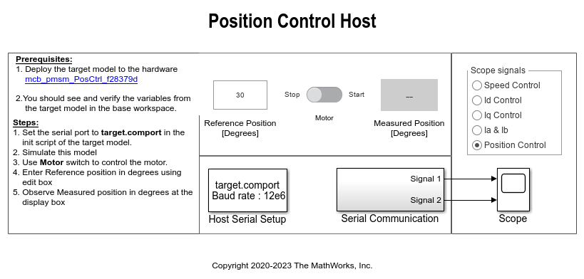
9. In the model initialization script associated with the target model, specify the communication port using the variable target.comport. The example uses this variable to update the Port parameter of the Host Serial Setup, Host Serial Receive, and Host Serial Transmit blocks available in the host model.
10. Update the Reference Position [Degrees] value in the host model. By default, the maximum number of rotations (in either the positive or negative direction) is five. You can change this value by setting the PosCtrlPosLimit variable in the model initialization script. You can open this script by using the hyperlink named Init script in the target model.
Maximum rotation limit (degrees) = PosCtrlPosLimit x 360
Note: You cannot control the speed of rotation of the motor, but you can limit it by setting the PosCtrlSpeedLimit variable (in per-units). For details about the per-unit system, see Per-Unit System.
11. Click Run on the Simulation tab to run the host model.
12. Change the position of the Start / Stop Motor switch to Start, to start running the motor.
13. Observe the debug signals from the RX subsystem, in the Time Scope of host model. You can select the debug signals that you want to monitor in the Scope signals section of the host model.
Speed Control - Display speed reference and speed feedback signals in the scope.
Id Control - Display Id reference and Id feedback signals in the scope.
Iq Control - Display Iq reference and Iq feedback signals in the scope.
Ia & Ib - Display Ia and Ib current signals in the scope.
Position Control - Display position reference and position feedback signals in the scope.