Main Content

PLL with Feed Forward

Compute position and angular frequency from orthogonal sinusoidal signals

Since R2023b

Libraries:
Motor Control Blockset / Signal Management

Description

The PLL with Feed Forward block computes angular position (θ) or its sine and cosine equivalents (sin θ, cos θ) and the angular frequency (ω) from two orthogonal sinusoidal signals.

In addition to the angular frequency, the block uses either a sine-cosine lookup table to calculate the angular position or an oscillator based algorithm to compute the sine and cosine equivalents of position. You can use the Position output parameter to output either angular position or its sine and cosine equivalents.

The two orthogonal sinusoidal input signals must have identical peak magnitudes. If the inputs are not normalized in the range of [-1,1], select the Enable input normalization parameter.

The following image shows the relationship between block inputs and outputs:

For more information on the block algorithm, see Algorithm.

Note

The block does not support 16-bit fixed-point inputs.

Examples

Ports

Input

expand all

Input signal along the α-axis.

Data Types: single | double | fixed point

Input signal along the β-axis.

Data Types: single | double | fixed point

External pulse that resets the block.

Data Types: single | double | fixed point

Output

expand all

Angular position (in either degrees, radians, or per-unit) that the block computes from the orthogonal input signals.

Dependencies

To enable this port, set the Position output parameter to Angular position.

Data Types: single | double | fixed point

Sine equivalent of the computed angular position.

Dependencies

To enable this port, set the Position output parameter to Sine and Cosine Position.

Data Types: single | double | fixed point

Cosine equivalent of the computed angular position.

Dependencies

To enable this port, set the Position output parameter to Sine and Cosine Position.

Data Types: single | double | fixed point

Angular frequency (in either degrees/sec, radians/sec, or hertz) of the orthogonal input signals.

Data Types: single | double | fixed point

Parameters

expand all

The block normalizes the α and β orthogonal input signals only if you select this parameter.

Type of position output that the block should generate:

  • Angular position — Select this option to use a sine-cosine lookup table to compute the angular position (θ).

  • Sine and Cosine Position — Select this option to use an oscillator based algorithm to compute the sine and cosine equivalents (sin θ and cos θ) of the angular position.

The fixed time interval (in seconds) between consecutive instances of block execution.

PLL Parameters

The ratio of the frequency of the output signal to the frequency of the input signal of the block.

Maximum possible frequency of the input signals (in hertz).

Cutoff frequency of the lowpass filter that the block uses to filter the estimated angular frequency (in hertz).

Size of the lookup table array that the block provides to the SinCos Embedded Optimized block, which is used internally. This parameter accepts a value between 125 and 4095.

Dependencies

To enable this parameter, set Position output to Angular position.

Proportional gain (Kp) of the PID controller used by the block to compute the angular frequency.

Integral gain (Ki) of the PID controller used by the block to compute the angular frequency.

Click Compute default parameters to calculate an approximate proportional gain (Kp) and integral gain (Ki) and update these fields.

Datatypes

Unit of the position output.

Dependencies

To enable this parameter, set Position output to Angular position.

Data type of the position output.

Unit of the angular frequency output.

Data type of the angular frequency output.

Data type of the sine-cosine lookup table used by the block.

Dependencies

To enable this parameter, set Position output to Angular position.

Algorithms

expand all

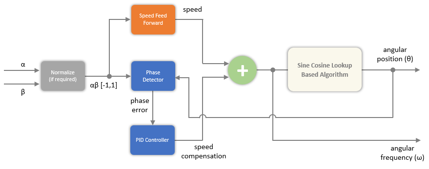
The following image provides an overview of how the block uses an algorithm based on sine-cosine lookup table to compute the angular position (θ). Set the Position output to Angular position to use this algorithm.

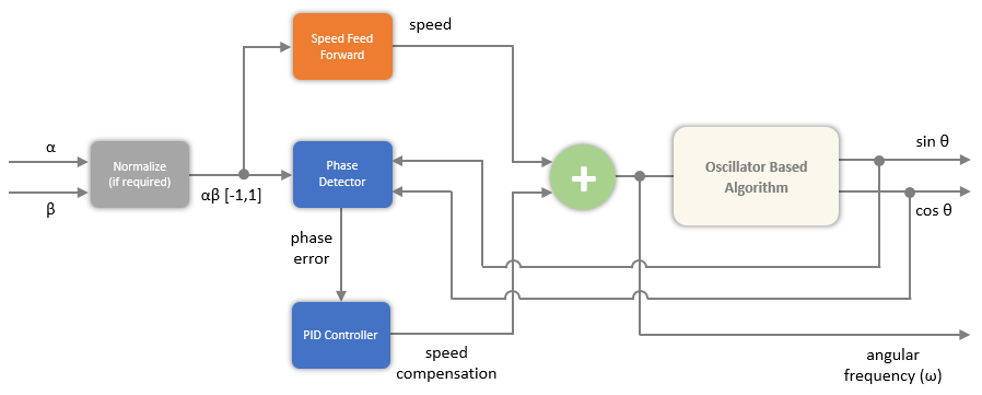
The following image provides an overview of how the block uses an oscillator-based algorithm to compute the sine and cosine equivalents of angular position (θ). Set the Position output to Sine and Cosine Position to use this algorithm.

The following equation describes the state equation of the oscillator-based algorithm.

x˙=[0ωω0]x

where, ω is the frequency of oscillation.

References

[1] G. Liu, H. Zhang and X. Song, "Position-Estimation Deviation-Suppression Technology of PMSM Combining Phase Self-Compensation SMO and Feed-Forward PLL," in IEEE Journal of Emerging and Selected Topics in Power Electronics, vol. 9, no. 1, pp. 335-344, Feb. 2021, doi: 10.1109/JESTPE.2020.2967508.

[2] Se-Kyo Chung, "A phase tracking system for three phase utility interface inverters," in IEEE Transactions on Power Electronics, vol. 15, no. 3, pp. 431-438, May 2000, doi: 10.1109/63.844502.

[3] Sreeraman Rajan, Sichun Wang, Robert Inkol, and Alain Joyal. "Efficient Approximations for the Arctangent Function." IEEE SIGNAL PROCESSING MAGAZINE (MAY 2006).

Extended Capabilities

C/C++ Code Generation
Generate C and C++ code using Simulink® Coder™.

Version History

Introduced in R2023b
Go to top of page