Evaluating Interference from 5G New Radio (NR) Signals at an Airport Surveillance Radar
As the frequency range of 5G NR systems increase beyond the bands used in LTE, spectrum management becomes more complex. The demand for expanded 5G coverage is driven by the benefits of higher data rates and lower latencies. The implementation of new 5G base stations in turn drives the need to understand how these signals affect installed systems that operate around the same frequency bands. One such system is an air traffic control radar.
In this example, you will learn how to model an air traffic control radar which operates in the vicinity of a 5G base station. We will look at how 5G signals affect the received radar signals. We use a scenario with an aircraft approaching the airport from the same direction as the base station. The radar return from the aircraft is processed with and without the presence of the 5G waveform.
Many different mitigation techniques can be applied to reduce interference, but in this example, we implement a beamformer at the base station that reduces transmitted energy in the direction of the radar.
Scenario
We first set up a scenario with the basestation location based on guidance in the 3GPP TR 38.901 specification. The base station is mounted on a rooftop on a building at a distance of 2.5 km from the airport.
The airport radar model is based on an Airport Surveillance Radar (ASR-11).
An aircraft is approaching the radar from the same direction as the base station.
Scatterers are added to the scenario to account for multipath reflections due to buildings in the path between the aircraft and the radar.
% Airport Radar position
asrPos=[0; 0; 15];
asrAxes = eye(3);
asrVel = [0; 0; 0];

% 5G Base Station position
bsPos = [2.5e+03; 0; 25];
bsAxes = rotz(180);

% Approaching aircraft starting position and velocity
targetPos = [50E3;0;450];
targetVel = [0;0;0];

% Channel parameters

% Generate 15 scatterers at random positions
rng(2021);                          % Initialize random number generator
numScat = 15;
azRange = -180:+180;
randAzOrder = randperm(length(azRange));
elRange = 0;
rRange = 0.5e3 : 2.5 : 1e3;
randROrder = randperm(length(rRange));
azAngInSph = deg2rad(azRange(randAzOrder(1:numScat)));
elAngInSph = zeros(size(azAngInSph));
r = (rRange(randROrder(1:numScat)));

% Transform spherical coordinates to Cartesian coordinates
[x,y,z] = sph2cart(azAngInSph,elAngInSph,r);
scatPos = [x;y;z] + bsPos;

scatCoef = ones(numScat,1)*1e-1;
You can plot the location of the 5G tower, the radar, and the scatterers.
figure; hold on; grid on;
plot3(asrPos(1),asrPos(2),asrPos(3),...
    'color','b','marker','o','MarkerFaceColor','b', ...
    'DisplayName','Airport Radar')
plot3(scatPos(1,:),scatPos(2,:),scatPos(3,:), ...
    'LineStyle','none','color','k','marker','square','MarkerFaceColor','k', ...
    'DisplayName','Scatterers')
plot3(bsPos(1),bsPos(2),bsPos(3), ...
    'color','r','marker','hexagram','MarkerFaceColor','r', ...
    'DisplayName','Base Station')
xlabel('X (m)'); ylabel('Y (m)'); legend('location','best')

Radar Configuration
You configure a radar model to match the parameters of an Airport Surveillance Radar (ASR-11).
fc     = 2.8e9;                     % Radar carrier frequency (Hz)
c      = physconst('Lightspeed');   % Propagation speed (m/s)
lambda = c/fc;                      % Radar wavelength (m)
The radar transmits a linear FM waveform.
asrSamplingFrequency = 1e6; %  (Hz)
PRF = 1000;                 % Pulse Repition Frequency (Hz)
dutyCycle = 0.1;


asrWaveform = phased.LinearFMWaveform( ...
    'SampleRate', asrSamplingFrequency, ...
    'DurationSpecification', 'Duty cycle', ...
    'DutyCycle', dutyCycle, ...
    'PRF', PRF);
The ASR-11 uses a parabolic reflector with a horn exciter. You can use an antenna element from Antenna Toolbox to generate the design.
rad=2.5;        % radius [m]
flen=2.5;       % focal length
% Create antenna
% (create)
asrAntennaElement=design(reflectorParabolic('Exciter',horn),fc);
% (orient)
asrAntennaElement.Exciter.Tilt=90;
asrAntennaElement.Exciter.TiltAxis=[0 1 0];
asrAntennaElement.Tilt=90;
asrAntennaElement.TiltAxis=[0 1 0];
% (params)
asrAntennaElement.Radius=rad;
asrAntennaElement.FocalLength=flen;

% (final create)
asrAntenna = phased.ConformalArray('Element',asrAntennaElement);


asrRadiator = phased.Radiator('OperatingFrequency',fc,...
    'Sensor', asrAntenna);
Define the radar transmitter
asrPower = 25000; % [W]
asrGain = 32.8; % [dB]
asrTransmitter = phased.Transmitter('PeakPower',asrPower, ...
    'Gain',asrGain);
Define the radar receiver antenna array and he receiver pre-amplifier.
asrCollector = phased.Collector('OperatingFrequency', fc, ...
    'Sensor', asrAntenna);

asrReceiver = phased.ReceiverPreamp( 'SampleRate', asrSamplingFrequency, ...
    'Gain', 20, ...
    'NoiseMethod','Noise temperature',...
    'NoiseFigure',6.31);
Define the approaching aircraft with radar cross section of 5m^2.
radarTarget = phased.RadarTarget(...
    'MeanRCS',5, ...
    'OperatingFrequency',fc);
Define the radar signal propagation environment as free space.
radarEnv = phased.FreeSpace('TwoWayPropagation',true, ...
    'SampleRate', asrSamplingFrequency, ...
    'OperatingFrequency', fc, ...
    'PropagationSpeed', c);
Base Station Configuration
You can generate a range of 5G waveforms using 5G Toolbox. Waveform data for this example is loaded from the referenced .mat file.
load helperRadarNRInterferenceData.mat
bsSamplingFrequency = waveStruct.Fs;
bsWaveform = waveStruct.waveform;
You define a base station antenna array based on the specification in 3GPP TR 28.901:
bsArray = phased.NRRectangularPanelArray('Size', [3, 2, 2, 2], ...
    'Spacing',[0.5*lambda, 0.5*lambda, 3*lambda, 3*lambda]);

bsSteeringVec = phased.SteeringVector('SensorArray',bsArray, ...
    'PropagationSpeed',c);

% Gain per antenna element
bsTxPower = 9; % watts
bsTxGain = -8; % dB
bsNumArrayElements = prod(bsArray.Size);
bsTransmitter = phased.Transmitter(...
    'PeakPower',bsTxPower/bsNumArrayElements, ...
    'Gain',bsTxGain);

[bs2asrRange, bs2asrAngle] = rangeangle(asrPos,bsPos,rotz(180));

bsArrayWeights = bsSteeringVec(fc,bs2asrAngle(1)+1);
bsArray.Taper = bsArrayWeights;

% Channel for base station signal
bsChannel = phased.ScatteringMIMOChannel('TransmitArray',bsArray,...
    'ReceiveArray',asrAntenna,...
    'CarrierFrequency',fc,...
    'SpecifyAtmosphere',true,...
    'SampleRate',bsSamplingFrequency,...
    'SimulateDirectPath',true,...
    'MaximumDelaySource','Property',...
    'MaximumDelay',1e-4,...
    'TransmitArrayMotionSource','Property',...
    'TransmitArrayPosition',bsPos,...
    'TransmitArrayOrientationAxes',bsAxes,...
    'ReceiveArrayMotionSource', 'Property', ...
    'ReceiveArrayPosition', asrPos, ...
    'ReceiveArrayOrientationAxes', asrAxes, ...
    'ScattererSpecificationSource','Property',...
    'ScattererPosition',scatPos,...
    'ScattererCoefficient',scatCoef');
Received Signals Generation
You simulate the radar return and the 5G signal propagation to generate the received signal at the radar receiver.
Simulating the Radar Return
The simulation steps to transmit and receive the radar signals follow. Note that the antenna dish of ASR-11 normally rotates and this can be modeled as well but for this example, we consider the simplified case where the ASR-11 is pointing toward the base station. In reality, the scatterers defined in the MIMO channel would cause multipath effects and generate radar reflections. However, these reflections are cancelled by signal processing techniques such as moving target indicator (MTI) processing. To simplify the simulation without loss of generality, we model the radar signal propagation in free space.
asrSignal = asrWaveform();
asrAmplifiedSignal = asrTransmitter(asrSignal);

[asr2TragetRange, asr2TargetAngle] = ...
    rangeangle(targetPos,asrPos);

asrRadiatedSignal = asrRadiator(asrAmplifiedSignal, ...
    asr2TargetAngle);

asrPropagatedSignal = radarEnv(...
    asrRadiatedSignal, ...
    asrPos,...
    targetPos,...
    asrVel, ...
    targetVel);


asrTargetReflection = radarTarget(asrPropagatedSignal);

asrCollectedSignal = asrCollector(asrTargetReflection, ...
    asr2TargetAngle);
Simulating the 5G Signal Propagation
The 5G signal is propagated form the base station to the radar system.
bsAmplifiedSignal = bsTransmitter(bsWaveform);
bsCollectedSignal = bsChannel(repmat(bsAmplifiedSignal,1,2*bsNumArrayElements));
Sampling Base Station and Radar Signals
You resample the received 5G signal to match the sampling frequency of the radar.
asrNsamples = length(asrSignal);
asrTvec = (0:asrNsamples-1)/asrSamplingFrequency;

bsNsamples = length(bsWaveform);
bsTvec = (0:bsNsamples-1)/bsSamplingFrequency;
bsCollectedSignal_Resampled = interp1( ...
    bsTvec,bsCollectedSignal,asrTvec).';

ReceivedSignal = asrReceiver(asrCollectedSignal + bsCollectedSignal_Resampled );
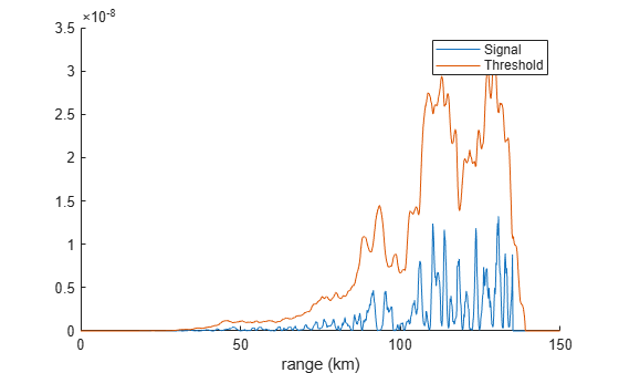
Signal Processing
You apply matched filtering, time variying gain, and CFAR detection to detect the target in the received signal.
% Matched filter
coeff = getMatchedFilter(asrWaveform);
mf = phased.MatchedFilter('Coefficients',coeff,'GainOutputPort',true);
matchingdelay = size(coeff,1)-1;

% Time varying gain
rgates = asrTvec*3e8/2;
tvg = phased.TimeVaryingGain(...
    'RangeLoss',2*fspl(rgates,lambda),...
    'ReferenceLoss', ...
    2*fspl(asrNsamples/asrSamplingFrequency*c/2,lambda));

% CFAR Detector
cfar = phased.CFARDetector('NumTrainingCells',50,'NumGuardCells',2);
cfar.ThresholdFactor = 'Custom';
cfar.CustomThresholdFactor = 6;
cfar.ThresholdOutputPort = true;


[sigp,Gmf] = mf(ReceivedSignal);
sigp = buffer(sigp(matchingdelay+1:end),size(sigp,1));


sigp = tvg(sigp);
[detected, th] = cfar(abs(sigp).^2,1:length(sigp));

figure; hold on;
plot(rgates*1e-3,abs(sigp).^2);
plot(rgates*1e-3,th);
plot(rgates(detected)*1e-3,abs(sigp(detected)).^2,'o','markersize',10)
legend('Signal','Threshold');
xlabel('range (km)');
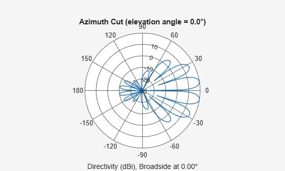
5G Base Station Beamforming
To eliminate the interference, a beamformer is added to the base station. Since the location of the airport radar is fixed, a null can be placed at this direction.
release(bsChannel)
% Calculate the steering vector for null directions
wn = bsSteeringVec(fc,bs2asrAngle(1));

% Calculate the steering vectors for lookout directions
bsLookAngle = 1; % Note: This angle should be different than the null angle.
wd = bsSteeringVec(fc,bsLookAngle);

% Compute the response of desired steering at null direction
rn = wn'*wd/(wn'*wn);

% Sidelobe canceler - remove the response at null direction
bsArrayWeights = wd-wn*rn;

bsChannel.TransmitArray.Taper = bsArrayWeights;
figure;
pattern(bsChannel.TransmitArray,fc,-180:180,0)
Simulating the 5G Signal Propagation after Beamforming
bsCollectedSignal_BF = bsChannel(repmat(bsAmplifiedSignal,1,2*bsNumArrayElements));
bsCollectedSignal_BF_Resampled = interp1( ...
    bsTvec,bsCollectedSignal_BF,asrTvec).';

ReceivedSignal_BF = asrReceiver(asrCollectedSignal + bsCollectedSignal_BF_Resampled);
[sigp_BF,Gmf_BF] = mf(ReceivedSignal_BF); sigp_BF = buffer(sigp_BF(matchingdelay+1:end),size(sigp_BF,1)); sigp_BF = tvg(sigp_BF); [detected_BF, th_BF] = cfar(abs(sigp_BF).^2,1:length(sigp_BF));
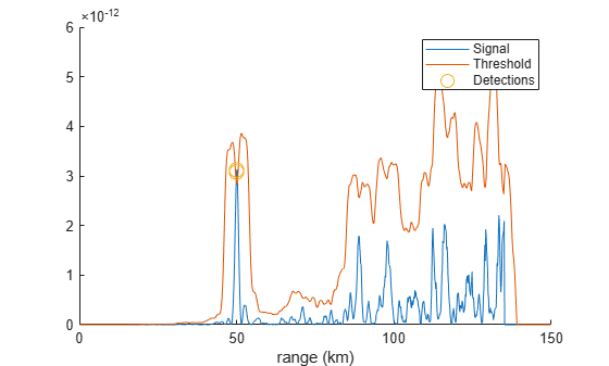
With beamforming in place, the signal level from the base station as seen by the radar is reduced such that it doesn’t interfere with the radar return.
figure; hold on;
plot(rgates*1e-3,abs(sigp_BF.^2));
plot(rgates*1e-3,th_BF);
plot(rgates(detected_BF)*1e-3,abs(sigp_BF(detected_BF)).^2,'o','markersize',10)
legend('Signal','Threshold','Detections');
xlabel('range (km)');
You can also select a web site from the following list:
Americas
- América Latina (Español)
- Canada (English)
- United States (English)
Europe
- Belgium (English)
- Denmark (English)
- Deutschland (Deutsch)
- España (Español)
- Finland (English)
- France (Français)
- Ireland (English)
- Italia (Italiano)
- Luxembourg (English)
- Netherlands (English)
- Norway (English)
- Österreich (Deutsch)
- Portugal (English)
- Sweden (English)
- Switzerland
- United Kingdom (English)