Main Content

EdgeFeed

Create an edge feed object

Since R2024b

    Description

    Use the EdgeFeed object to create and specify the FeedDefinitions property in a parent pcbComponent object.

    Creation

    Description

    f1=EdgeFeed creates a defaultEdgeFeed object.

    f1=EdgeFeed(name=value) sets object properties using one or more name value arguments.

    example

    Properties

    expand all

    Specifies the location to be positively excited as a 1x2 matrix in meters.

    The first and the second columns correspond to the X and Y coordinates in meters, respectively. This location must lie on the edge of a metal layer. Locations of negative excitation are assumed to lie directly above (+z) and/or below (-z) the location of positive excitation.

    Example: f1=EdgeFeed;f1.SignalLocations=[-0.02,0]

    Data Types: double

    Example: f1=EdgeFeed;f1.SignalLayers=2

    Data Types: double

    Specifies the board layers for all negative excitation sites as a Nx1 matix in meters.

    Example: f1=EdgeFeed;f1.GroundLayers=5

    Data Types: double

    Specifies the width of the positive excitation site as a scalar, in meters.

    Example: f1=EdgeFeed;f1.SignalWidths=0.003

    Data Types: double

    Examples

    collapse all

    This example shows how to instantiate EdgeFeed objects to excite a pcbComponent in stripline configuration.

    Convert the default pcbComponent from microstrip format to stripline format by copying its bottom two layers to the top of the layer stack.

    p = pcbComponent;
    layersTemp = p.Layers;
    p.BoardThickness = p.BoardThickness * 2;
    p.Layers = [layersTemp(3), layersTemp(2), layersTemp];

    The default FeedLocations property has the correct positions for the two feeds. Save this information to a temporary variable and switch the FeedFormat property to 'FeedDefinitions' to expose the pcbComponent's FeedDefinitions property.

    feedsTemp = p.FeedLocations;
    p.FeedFormat = 'FeedDefinitions';

    Introduce two EdgeFeed objects to excite the strip against both ground planes simultaneously. The second is a copy of the first with an updated position.

    f1 = EdgeFeed('SignalLocations', feedsTemp(1, 1:2), 'SignalLayers', 3, 'GroundLayers', [1; 5], 'SignalWidths', p.Layers{3}.Width);
    f2 = copy(f1);
    f2.SignalLocations = feedsTemp(2, 1:2);

    Write the EdgeFeed objects to the pcbComponent's FeedDefinitions property, then show the pcbComponent and calculate its S-parameters.

    p.FeedDefinitions = [f1 f2];
    
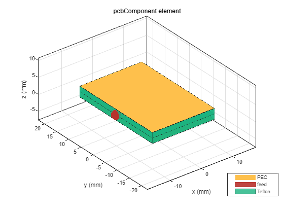
    figure; show(p);

    Figure contains an axes object. The axes object with title pcbComponent element, xlabel x (mm), ylabel y (mm) contains 10 objects of type patch, surface. These objects represent PEC, feed, Teflon.

    s = sparameters(p, linspace(1e9, 5e9, 10));
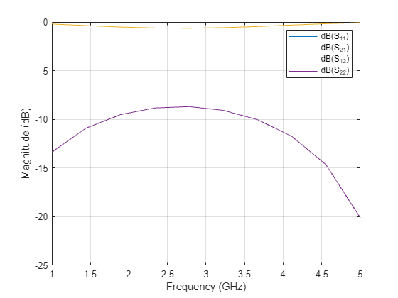
    figure; rfplot(s);

    Figure contains an axes object. The axes object with xlabel Frequency (GHz), ylabel Magnitude (dB) contains 4 objects of type line. These objects represent dB(S_{11}), dB(S_{21}), dB(S_{12}), dB(S_{22}).

    Version History

    Introduced in R2024b