Main Content

FiniteGapFeed

Create a finite gap feed object

Since R2024b

    Description

    Use the FiniteGapFeed object to create and specify the FeedDefinitions property in a parent pcbComponent object.

    Creation

    Description

    f1=FiniteGapFeed creates a default FiniteGapFeed object.

    f1=FiniteGapFeed(name=value) set properties using one or more name value arguments.

    example

    Properties

    expand all

    Specifies the locations that require positive excitation as a matrix of size Nx2 in meters.

    The first and second columns correspond to the x and Y coordinates, receptively, in meters. Each location must lie on the edge of a metal layer.

    Example: f1=FiniteGapFeed;f1.SignalLocations=[0.002,0]

    Data Types: double

    Specifies the locations that require negative excitation as a matrix of size Nx2 in meters.

    The first and second columns correspond to the x and Y coordinates, receptively, in meters. Each location must lie on the edge of a metal layer.

    Example: f1=FiniteGapFeed;f1.GroundLocations=[-0.02,0]

    Data Types: double

    Specifies the metal layer on which the positive and negative excitation sites lie as a scalar

    Example: f1-FiniteGapFeed;f1.SignalLayers=2

    Data Types: double

    Specifies the width of each excitation site as a Nx1 matrix in meters. The metal edges on which SignalLocations(n,:) and GroundLocations(n,:) lie must be longer than or equal to SignalWidths(n).

    Example: f1=FiniteGapFeed;f1.SignalWidths=0.003

    Data Types: double

    Examples

    collapse all

    This example shows how to use a FiniteGapFeed object to define an internal port on a pcbComponent object.

    Start with the wilkinsonSplitter catalog element and convert it to a pcbComponent. Save its resistor length.

    w = wilkinsonSplitter;
    rL = w.ResistorLength;
    p = pcbComponent(w);

    The catalog element has a lumped load bridging the two output terminals. Save its location, replace it by the placeholder lumpedElement, and delete the leftover metal strip.

    internalPortLocation = p.Load.Location;
    p.Load = lumpedElement;
    rectangleCut = traceRectangular('Center', internalPortLocation(1:2), 'Length', 0.5e-3, 'Width', rL);
    p.Layers{1} = p.Layers{1} - rectangleCut;

    Switch the pcbComponent object's FeedFormat property to 'FeedDefinitions' to expose the FeedDefinitions property. Instantiate a FiniteGapFeed at the saved lumped load site and add it to the list of feeds.

    p.FeedFormat = 'FeedDefinitions';
    f = FiniteGapFeed('SignalLocations', internalPortLocation(1:2) + [0 rL/2], 'GroundLocations', internalPortLocation(1:2) + [0 -rL/2], 'SignalLayers', 1, 'SignalWidths', 0.5e-3);
    p.FeedDefinitions(end+1) = f;
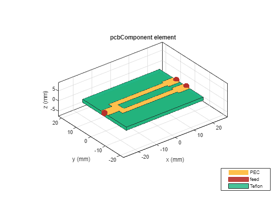
    figure; show(p);

    Figure contains an axes object. The axes object with title pcbComponent element, xlabel x (mm), ylabel y (mm) contains 9 objects of type patch, surface. These objects represent PEC, feed, Teflon.

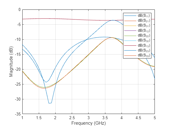
    Calculate 4-port S-parameters for the splitter. Terminate the internal port into a 100-ohm resistance and plot the result.

    s = sparameters(p, linspace(1e9, 5e9, 51));
    s100 = snp2smp(s, 1:3, 100);
    figure; rfplot(s100)

    Figure contains an axes object. The axes object with xlabel Frequency (GHz), ylabel Magnitude (dB) contains 9 objects of type line. These objects represent dB(S_{11}), dB(S_{21}), dB(S_{31}), dB(S_{12}), dB(S_{22}), dB(S_{32}), dB(S_{13}), dB(S_{23}), dB(S_{33}).

    Version History

    Introduced in R2024b