Plan a Reaching Trajectory with Multiple Kinematic Constraints
This example shows how to use generalized inverse kinematics to plan a joint-space trajectory for a robotic manipulator. It combines multiple constraints to generate a trajectory that guides the gripper to a cup resting on a table. These constraints ensure that the gripper approaches the cup in a straight line and that the gripper remains at a safe distance from the table, without requiring the poses of the gripper to be determined in advance.
Set Up the Robot Model
This example uses a model of the KUKA LBR iiwa, a 7 degree-of-freedom robot manipulator. importrobot generates a rigidBodyTree model from a description stored in a Unified Robot Description Format (URDF) file.
lbr = importrobot('iiwa14.urdf'); % 14 kg payload version
lbr.DataFormat = 'row';
gripper = 'iiwa_link_ee_kuka';
Define dimensions for the cup.
cupHeight = 0.2;
cupRadius = 0.05;
cupPosition = [-0.5, 0.5, cupHeight/2];
Add a fixed body to the robot model representing the center of the cup.
body = rigidBody('cupFrame');
setFixedTransform(body.Joint, trvec2tform(cupPosition))
addBody(lbr, body, lbr.BaseName);
Define the Planning Problem
The goal of this example is to generate a sequence of robot configurations that satisfy the following criteria:
Start in the home configuration
No abrupt changes in robot configuration
Keep the gripper at least 5 cm above the "table" (z = 0)
The gripper should be aligned with the cup as it approaches
Finish with the gripper 5 cm from the center of the cup
This example utilizes constraint objects to generate robot configurations that satisfy these criteria. The generated trajectory consists of five configuration waypoints. The first waypoint, q0, is set as the home configuration. Pre-allocate the rest of the configurations in qWaypoints using repmat.
numWaypoints = 5;
q0 = homeConfiguration(lbr);
qWaypoints = repmat(q0, numWaypoints, 1);
Create a generalizedInverseKinematics solver that accepts the following constraint inputs:
Cartesian bounds - Limits the height of the gripper.
A position target - Specifies the position of the cup relative to the gripper.
An aiming constraint - Aligns the gripper with the cup axis.
An orientation target - Maintains a fixed orientation for the gripper while approaching the cup.
Joint position bounds - Limits the change in joint positions between waypoints.
gik = generalizedInverseKinematics('RigidBodyTree', lbr, ...
    'ConstraintInputs', {'cartesian','position','aiming','orientation','joint'})
gik =
  generalizedInverseKinematics with properties:

      NumConstraints: 5
    ConstraintInputs: {'cartesian'  'position'  'aiming'  'orientation'  'joint'}
       RigidBodyTree: [1x1 rigidBodyTree]
     SolverAlgorithm: 'BFGSGradientProjection'
    SolverParameters: [1x1 struct]
Create Constraint Objects
Create the constraint objects that are passed as inputs to the solver. These object contain the parameters needed for each constraint. Modify these parameters between calls to the solver as necessary.
Create a Cartesian bounds constraint that requires the gripper to be at least 5 cm above the table (negative z direction). All other values are given as inf or -inf.
heightAboveTable = constraintCartesianBounds(gripper);
heightAboveTable.Bounds = [-inf, inf; ...
                           -inf, inf; ...
                           0.05, inf]
heightAboveTable =
  constraintCartesianBounds with properties:

        EndEffector: 'iiwa_link_ee_kuka'
      ReferenceBody: ''
    TargetTransform: [4x4 double]
             Bounds: [3x2 double]
            Weights: [1 1 1]
Create a constraint on the position of the cup relative to the gripper, with a tolerance of 5 mm.
distanceFromCup = constraintPositionTarget('cupFrame');
distanceFromCup.ReferenceBody = gripper;
distanceFromCup.PositionTolerance = 0.005
distanceFromCup =
constraintPositionTarget with properties:
EndEffector: 'cupFrame'
ReferenceBody: 'iiwa_link_ee_kuka'
TargetPosition: [0 0 0]
PositionTolerance: 0.0050
Weights: 1
Create an aiming constraint that requires the z-axis of the iiwa_link_ee frame to be approximately vertical, by placing the target far above the robot. The iiwa_link_ee frame is oriented such that this constraint aligns the gripper with the axis of the cup.
alignWithCup = constraintAiming('iiwa_link_ee');
alignWithCup.TargetPoint = [0, 0, 100]
alignWithCup =
constraintAiming with properties:
EndEffector: 'iiwa_link_ee'
ReferenceBody: ''
TargetPoint: [0 0 100]
AngularTolerance: 0
Weights: 1
Create a joint position bounds constraint. Set the Bounds property of this constraint based on the previous configuration to limit the change in joint positions.
limitJointChange = constraintJointBounds(lbr)
limitJointChange =
  constraintJointBounds with properties:

     Bounds: [7x2 double]
    Weights: [1 1 1 1 1 1 1]
Create an orientation constraint for the gripper with a tolerance of one degree. This constraint requires the orientation of the gripper to match the value specified by the TargetOrientation property. Use this constraint to fix the orientation of the gripper during the final approach to the cup.
fixOrientation = constraintOrientationTarget(gripper);
fixOrientation.OrientationTolerance = deg2rad(1)
fixOrientation =
  constraintOrientationTarget with properties:

             EndEffector: 'iiwa_link_ee_kuka'
           ReferenceBody: ''
       TargetOrientation: [1 0 0 0]
    OrientationTolerance: 0.0175
                 Weights: 1
Find a Configuration That Points at the Cup
This configuration should place the gripper at a distance from the cup, so that the final approach can be made with the gripper properly aligned.
intermediateDistance = 0.3;
Constraint objects have a Weights property which determines how the solver treats conflicting constraints. Setting the weights of a constraint to zero disables the constraint. For this configuration, disable the joint position bounds and orientation constraint.
limitJointChange.Weights = zeros(size(limitJointChange.Weights));
fixOrientation.Weights = 0;
Set the target position for the cup in the gripper frame. The cup should lie on the z-axis of the gripper at the specified distance.
distanceFromCup.TargetPosition = [0,0,intermediateDistance];
Solve for the robot configuration that satisfies the input constraints using the gik solver. You must specify all the input constraints. Set that configuration as the second waypoint.
[qWaypoints(2,:),solutionInfo] = gik(q0, heightAboveTable, ...
                       distanceFromCup, alignWithCup, fixOrientation, ...
                       limitJointChange);
Find Configurations That Move Gripper to the Cup Along a Straight Line
Re-enable the joint position bound and orientation constraints.
limitJointChange.Weights = ones(size(limitJointChange.Weights));
fixOrientation.Weights = 1;
Disable the align-with-cup constraint, as the orientation constraint makes it redundant.
alignWithCup.Weights = 0;
Set the orientation constraint to hold the orientation based on the previous configuration (qWaypoints(2,:)). Get the transformation from the gripper to the base of the robot model. Convert the homogeneous transformation to a quaternion.
fixOrientation.TargetOrientation = ...
    tform2quat(getTransform(lbr,qWaypoints(2,:),gripper));
Define the distance between the cup and gripper for each waypoint.
finalDistanceFromCup = 0.05;
distanceFromCupValues = linspace(intermediateDistance, finalDistanceFromCup, numWaypoints-1);
Define the maximum allowed change in joint positions between each waypoint.
maxJointChange = deg2rad(10);
Call the solver for each remaining waypoint.
for k = 3:numWaypoints
    % Update the target position.
    distanceFromCup.TargetPosition(3) = distanceFromCupValues(k-1);
    % Restrict the joint positions to lie close to their previous values.
    limitJointChange.Bounds = [qWaypoints(k-1,:)' - maxJointChange, ...
                               qWaypoints(k-1,:)' + maxJointChange];
    % Solve for a configuration and add it to the waypoints array.
    [qWaypoints(k,:),solutionInfo] = gik(qWaypoints(k-1,:), ...
                                         heightAboveTable, ...
                                         distanceFromCup, alignWithCup, ...
                                         fixOrientation, limitJointChange);
end
Visualize the Generated Trajectory
Interpolate between the waypoints to generate a smooth trajectory. Use pchip to avoid overshoots, which might violate the joint limits of the robot.
framerate = 15;
r = rateControl(framerate);
tFinal = 10;
tWaypoints = [0,linspace(tFinal/2,tFinal,size(qWaypoints,1)-1)];
numFrames = tFinal*framerate;
qInterp = pchip(tWaypoints,qWaypoints',linspace(0,tFinal,numFrames))';
Compute the gripper position for each interpolated configuration.
gripperPosition = zeros(numFrames,3);
for k = 1:numFrames
    gripperPosition(k,:) = tform2trvec(getTransform(lbr,qInterp(k,:), ...
                                                    gripper));
end
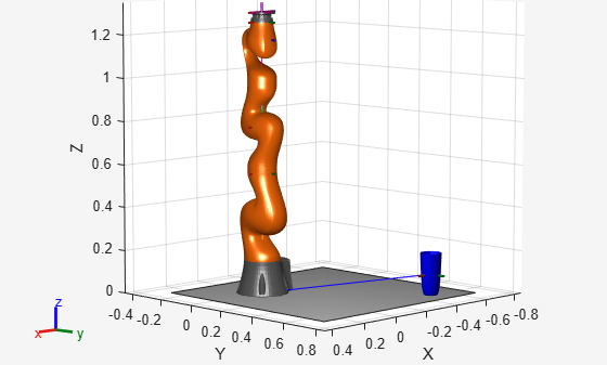
Show the robot in its initial configuration along with the table and cup.
figure;
show(lbr, qWaypoints(1,:), 'PreservePlot', false);
hold on
exampleHelperPlotCupAndTable(cupHeight, cupRadius, cupPosition);
p = plot3(gripperPosition(1,1), gripperPosition(1,2), gripperPosition(1,3));
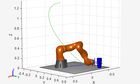
Animate the manipulator and plot the gripper position.
hold on
for k = 1:size(qInterp,1)
    show(lbr, qInterp(k,:), 'PreservePlot', false);
    p.XData(k) = gripperPosition(k,1);
    p.YData(k) = gripperPosition(k,2);
    p.ZData(k) = gripperPosition(k,3);
    waitfor(r);
end
hold off
If you want to save the generated configurations to a MAT-file for later use, execute the following:
>> save('lbr_trajectory.mat', 'tWaypoints', 'qWaypoints');
You can also select a web site from the following list:
Americas
- América Latina (Español)
- Canada (English)
- United States (English)
Europe
- Belgium (English)
- Denmark (English)
- Deutschland (Deutsch)
- España (Español)
- Finland (English)
- France (Français)
- Ireland (English)
- Italia (Italiano)
- Luxembourg (English)
- Netherlands (English)
- Norway (English)
- Österreich (Deutsch)
- Portugal (English)
- Sweden (English)
- Switzerland
- United Kingdom (English)