Integrated Encoder Module
Measure the rotation of a motor in ticks
Add-On Required: This feature requires the Simulink Coder Support Package for ARM Cortex-based VEX Microcontroller add-on.
Library
Simulink Coder Support Package for ARM Cortex-based VEX Microcontroller/Sensors
Description
Measure the rotation of a motor on which the sensor is installed, in ticks. For anti-clockwise rotation, the tick count increments and for clockwise rotation, the tick count decrements. The block outputs the tick count based on the motor type.
During simulations, without the hardware, this block emits zeros if no Source block is connected to the simulation input port. See Block Produces Zeros or Does Nothing in Simulation. To achieve simulation behavior, connect a Source block from the Utilities library in VEX Microcontroller library. During code generation, any simulation block that is connected to the input port of the Integrated Encoder Module block is ignored and has no effect on the generated code.
Parameters
- Motor type
Select the motor type on which the encoder is installed. The motor type determines the ticks per rotation.
- Sequence order from I2C port
Select the sequence number of the Integrated Encoder Module in the daisy chain. The sequence number starts from 0 assigned to the Integrated Encoder Module that is connected to I2C port and the next one with the sequence number 1 and so on.
- Reset mode
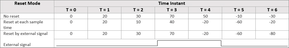
Select the reset mode for resetting the measured value of the encoder. In the example table shown below for reset modes, the block is assumed to have the tick count at time instant T = 0 is 0 and sample time 1 sec.
The different reset modes this block supports are as follows:
No reset– The measurement value is not reset and the block outputs the total ticks of rotation.For example, in the table below at T = 1, the encoder moves a tick count of 20 in anti-clockwise direction and therefore the output is 20. Between T = 1 and T = 2, the encoder moves a tick count of 10.
Therefore, the tick count is 30 at T = 2 ( 20 from T = 1 and 10 from T = 2). In this reset mode, the output at any time instant is a cumulative sum of the previous count and the current count.
Reset at each sample time– For each sample period, the block outputs the measurement value and then resets it to 0.For example, in the table below, at T = 1, the encoder moves a tick count of 20 in anti-clockwise direction and therefore the output is 20. Between T = 1 and T = 2, the encoder moves a tick count of 10 and therefore the output is 10. In this reset mode, the output is the tick count at a particular time instant.
Reset by external signal– The measurement value is reset to 0 based on the block input value. When you send a value other than 0 to the block input, the measurement value is reset to 0. For each sample period, the block outputs the measurement value since the last reset.For example in the table below, when the external signal is 0, the output is based on ‘No reset’ mode and when the external signal is non-zero, the output is based on ‘Reset at each sample time’ mode.
- Output rotational velocity
Select this check box to output the rotational velocity of the internal encoder wheel in revolutions per minute (rpm).
- Add input port for simulation
Select this check box, if you want the normal mode simulation with a source block providing the input value.
- Sample time
Specify how often this block reads the rotation, in seconds. If you select Add input port for simulation check box or select
Reset by external signaloption in Reset mode parameter, the Sample time parameter is hidden and the value is inherited (Sample time = -1).
Version History
Introduced in R2017a