Set Up Project Library in Serial Link Designer
The Serial Link Designer app uses search paths to find library elements like I/O buffer models, transmission line models and S-Parameter files. By default, when you create a new project or a new interface, the app automatically reference it in the local library of the project as well as the installation library.
To add a new library element, you must either create it through the Serial Link Designer app, import it by clicking Libraries in the app toolstrip, or copy it into the appropriate search path directory.
Library Structure and Search Paths
The Serial Link Designer app uses search paths to locate library parts, which provide an easy to use and flexible library management system. You can define and customize independent search paths for each category of model. The default configuration is a directory tree with separate directories for each model type.
By default, when the app searches a library, it first searches the local project directories and then the installation library.
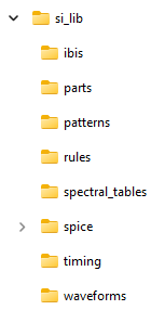
Library elements in the Serial Link Designer app are component-level
elements. The app uses the IBIS component as its component pinout, since it matches a pin
number, pin name and model name. IBIS files located in the si_lib\ibis
directory defines the multiple components such as IBIS models, AMI models, HSPICE I/O buffer
models, and package models for SPICE, s-parameters, and RLC transmission lines used in the
project.
In order to handle IBIS files and to allow other component-level information, the app uses a library element called a Part as the primary element. The app uses the file name and a search path to find library elements, so files must be placed in the correct library directory before the app can use them.
I/O Buffer Models
You can define the I/O buffer models in the Serial Link Designer app in two ways:
Using IBIS I/O buffer models — The I/O buffer model is defined in an IBIS file. The app uses a Part to access the IBIS model. You can use an IBIS model supplied by the manufacturer in pre-layout analysis or post-layout verification. You can also use an already imported IBIS model in post-layout verification.
Using SPICE I/O buffer models — The I/O buffer model is defined in an encrypted or unencrypted HSPICE I/O buffer model. The model is referenced from within an IBIS file. This allows the same Part and IBIS component structure to be used for IBIS models and HSPICE models. You also need to a SPICE wrapper and an AMI file with correct syntax to use HSPICE buffer models.
Technology Libraries
The app contains libraries of technology and generic models. You can assign the technology and generic library models to schematic designators. You can also use them to create default IBIS models in post-layout.
The models Si_Advanced_Tx (generic IBIS-AMI transmitter) and
Si_Advanced_Rx (generic IBIS-AMI receiver) contain all of the
functionality of the technology models. The other models expose a subset of the
functionality of the advanced models.
Parts
Parts associate an IBIS model and a timing model for a device. The part references an IBIS file and IBIS component in the IBIS file. The app refers the models through their part name during pre-layout analysis and through the CAD part Number during post-layout verification. You can customize the parts by defining IBIS and timing options. For more information, see Parts.
Transmission Line Models
You can use lossy transmission lines in the Serial Link Designer app in three ways:
Create Models in Standalone Library Mode — Quickly create different types of lossy models and store them in a library location using the Lossy Transmission Line Editor. To access the dialog box, select Tools > Lossy Transmission Line editor.
You can create a base model and one or more associated coupled models in a library directory. You can then refer the models in multiple projects and reuse them across designs. If you make changes to the common library models, the changes will be reflected in all the projects where the models are used.
Create Models in Interactive Mode — Create lossy models and coupled models on the fly for a selected transmission line schematic using the Lossy Transmission Line Editor. To access the editor, right click on the w-line element symbol in the schematic and select Edit T-line Properties.
Use Lossy Transmission Line Models from Other Sources — You can place lossy transmission line models from other sources and use them from pre-layout analysis. These model can be RLGC transmission line models created with the Lossy Transmission Line Editor or table transmission model files.
To use the table transmission models, place the model in a file with name
<model_name>.modin the directorysi_lib/spice/wlines. Right click on the w-line symbol you want to associate the model with, select Select T-Line Model, then select the file with the table model.
For more information about how the app models the transmission lines, see Model Lossy Transmission Lines in Serial Link Designer.
S-Parameters
You can import and analyze s-parameters in the Serial Link Designer app. The
app support S-parameter data in Touchstone file format (.sNp
files).
To use the S-parameters in analysis, you must place them in the library search path. You can use the import operation to create a wrapper and edit the port maps. After importing, you can:
combine the cross-talk S-parameters to create a larger s-parameter file, or
combine channel S-Parameters for different elements like connector models, transmission line models and others in series.
You can also evaluate check the S-parameter file for a step-by-step evaluation of the waveforms.
For more information, see S-Parameters in Serial Link Projects.
SPICE and S-Parameter Package Models
Spice or S-parameter package models are referenced from within the IBIS file for a component. The package files can be in the form of a SPICE subcircuit or a Touchstone compliant S-parameter model.