Highpass IIR
Design highpass infinite impulse response filter
Description
A highpass filter attenuates the energy of an input signal below a specified frequency threshold. An infinite impulse response (IIR) filter computes an output signal as a running weighted average of input samples and previous output values.
Signal Processing Toolbox™ provides different ways to design highpass IIR filters:
designfiltfunction — Design a highpass IIR filter at the command line or in a script. Use"highpassiir"as the first argument when you call the function.For an example, see Design Highpass IIR Filter Using designfilt.
Design Filter Live Editor task — Design a highpass IIR filter as part of a live script. The task displays code that you can paste into other MATLAB® programs.
For an example, see Design Highpass IIR Filter Using Live Editor Task.
Filter Designer app — Design a highpass IIR filter interactively. Export your design to the MATLAB workspace, to Simulink®, or to a file.
For an example, see Design Highpass IIR Filter Using Filter Designer.
All of these methods return digitalFilter objects. If you
have a DSP System Toolbox™ license, you can generate your design as a filter System object™ and include additional Design Method Options.
For other ways to design highpass IIR filters using MATLAB, see Other Highpass IIR Filter Design Functions.
Examples
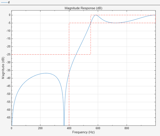
To design the filter at the command line or in a script, use the designfilt function with "highpassiir" as the first argument. Use name-value arguments to specify your design further.
d = designfilt("highpassiir", ...  % Response type
    SampleRate=2000, ...           % Sample rate
    StopbandFrequency=400, ...     % Frequency constraints
    PassbandFrequency=550, ...
    StopbandAttenuation=25, ...    % Magnitude constraints
    PassbandRipple=5, ...
    DesignMethod="ellip", ...      % Design method
    MatchExactly="passband", ...   % Design method options
    ScaleSOS=true);
filterAnalyzer(d)
To design the filter using the Design Filter Live Editor task:
Specify the filter:
Under Select filter response, select Highpass IIR.
Under Sample Rate, specify Frequency units as
Hzand Input sample rate (Hz) as2000.Under Specify frequency parameters, specify a stopband frequency of
400Hz and a passband frequency of550Hz.Under Specify magnitude parameters, specify a stopband attenuation of
25dB and a passband ripple of5dB.Under Specify algorithm, select
Elliptic. Under Specify algorithm options, specify that the design match thePassbandexactly.
The Live Editor task updates the filter automatically by default.

To design the filter using the Filter Designer app:
In the Response gallery of the Designer tab in the app toolstrip, select Highpass IIR.
Specify the filter using the options in the Filter Parameters table:
In Design by, select Specification.
In Sample Rate, specify Frequency units as
Hzand Input sample rate (Hz) as2000.Under Frequency Specifications, specify a stopband frequency of
400Hz and a passband frequency of550Hz.Under Magnitude Specifications, specify a stopband attenuation of
25dB and a passband ripple of5Hz.Under Algorithm, select
Elliptic. Under Algorithm Options, specify that the design match thePassbandexactly.
In the Filter section of the Designer tab, click Update Filter.

Export code to create your digital filter. On the toolstrip, click Export and select
Generate MATLAB function>Digital Filter Object. The code appears in the editor.function designedFilter = highpassiir1filt designedFilter = designfilt('highpassiir', ... 'StopbandFrequency',400,'PassbandFrequency',550, ... 'StopbandAttenuation',25,'PassbandRipple',5, ... 'SampleRate',2000,'DesignMethod','ellip', ... 'MatchExactly','passband','ScaleSOS',true); end
Parameters
Design Method
Specify the algorithm to design the filter. The available design methods correlate with the set of design specifications that you choose.
Design the filter using the Butterworth algorithm. Butterworth filters have a smooth monotonic frequency response that is maximally flat in the passband. They trade rolloff steepness for flatness.
designfilt Function | Design Filter Live Editor Task | Filter Designer App |
|---|---|---|
Specify | In the Specify algorithm section of the task, set Design
method to
| In the Algorithm section of the filter parameters panel, set
Design method to
|
The Butterworth design method supports these design parameter combinations.
| Filter Order | Frequency Specifications | Magnitude Specifications | Design Method Options | DSP System Toolbox License Required |
|---|---|---|---|---|
| N/A |
|
|
| |
|
| N/A | N/A | ||
|
|
| N/A | N/A |
Design the filter using the Chebyshev type I algorithm. Chebyshev type I filters have a frequency response that is equiripple in the passband and maximally flat in the stopband. Their passband ripple increases with increasing rolloff steepness.
designfilt Function | Design Filter Live Editor Task | Filter Designer App |
|---|---|---|
Specify
| In the Specify algorithm section of the
task, set Design method to
| In the Algorithm section of the filter
parameters panel, set Design method to
|
The Chebyshev type I design method supports these design parameter combinations.
| Filter Order | Frequency Specifications | Magnitude Specifications | Design Method Options | DSP System Toolbox License Required |
|---|---|---|---|---|
| N/A |
|
|
| |
|
|
| N/A | |
|
| N/A | N/A | ✓ |
|
|
| N/A | ✓ |
Design the filter using the Chebyshev type II algorithm. Chebyshev type II filters have a frequency response that is maximally flat in the passband and equiripple in the stopband.
designfilt Function | Design Filter Live Editor Task | Filter Designer App |
|---|---|---|
Specify
| In the Specify algorithm section of the
task, set Design method to
| In the Algorithm section of the filter
parameters panel, set Design method to
|
The Chebyshev type II design method supports these design parameter combinations.
| Filter Order | Frequency Specifications | Magnitude Specifications | Design Method Options | DSP System Toolbox License Required |
|---|---|---|---|---|
| N/A |
|
|
| |
|
|
| N/A | |
|
| N/A | N/A | ✓ |
|
|
| N/A | ✓ |
Design the filter using the elliptic algorithm. Elliptic filters have a frequency response that is equiripple in both passband and stopband.
designfilt Function | Design Filter Live Editor Task | Filter Designer App |
|---|---|---|
Specify | In the Specify algorithm section of the task, set Design
method to
| In the Algorithm section of the filter parameters panel, set
Design method to
|
The elliptic design method supports these design parameter combinations.
| Filter Order | Frequency Specifications | Magnitude Specifications | Design Method Options | DSP System Toolbox License Required |
|---|---|---|---|---|
| N/A |
|
|
| |
|
|
|
| N/A | |
|
|
|
| N/A | ✓ |
|
|
|
| N/A | ✓ |
Design the filter using the least Pth-norm unconstrained optimization algorithm.
You must have a DSP System Toolbox license to use this design method.
designfilt Function | Design Filter Live Editor Task | Filter Designer App |
|---|---|---|
Specify | In the Specify algorithm section of the task, set Design
method to | In the Algorithm section of the filter parameters panel, set
Design method to
|
The least Pth-norm method supports these design parameter combinations.
| Filter Order | Frequency Specifications | Magnitude Specifications | Design Method Options | DSP System Toolbox License Required |
|---|---|---|---|---|
|
|
| N/A |
| ✓ |
|
| N/A |
| ✓ |
Sample Rate
Specify the filter sample rate as a positive scalar expressed in hertz.
designfilt Function | Design Filter Live Editor Task | Filter Designer App |
|---|---|---|
| In the Sample Rate section of the task:
| In the Sample Rate section of the filter parameters panel:
|
Filter Order
Specify the filter order N as a positive integer. Some design methods let you specify the order. Others generate minimum-order designs, which are the shortest filters that satisfy the specified constraints.
designfilt Function | Design Filter Live Editor Task | Filter Designer App |
|---|---|---|
| In the Specify Filter Order section of the task:
| In the Filter Order section of the filter parameters panel:
|
Specify the numerator order as a positive integer.
designfilt Function | Design Filter Live Editor Task | Filter Designer App |
|---|---|---|
| In the Specify Filter Order section of the task:
| In the Filter Order section of the filter parameters panel:
|
Specify the denominator order as a positive integer.
designfilt Function | Design Filter Live Editor Task | Filter Designer App |
|---|---|---|
| In the Specify Filter Order section of the task:
| In the Filter Order section of the filter parameters panel:
|
Frequency Specifications
Specify the passband frequency as a positive scalar smaller than the Nyquist frequency. If you work with normalized frequencies, the Nyquist frequency is 1. If you specify a sample rate Fs, the Nyquist frequency is Fs/2.
The passband frequency is the lowest frequency for which the magnitude response of the filter is within an interval of width Passband Ripple from the reference value, usually 0 dB.
designfilt Function | Design Filter Live Editor Task | Filter Designer App |
|---|---|---|
|
|
|
Specify the stopband frequency as a positive scalar smaller than the Nyquist frequency. If you work with normalized frequencies, the Nyquist frequency is 1. If you specify a sample rate Fs, the Nyquist frequency is Fs/2.
The stopband frequency is the highest frequency for which the magnitude response of the filter is at least Stopband Attenuation dB lower than the reference value, usually 0 dB.
designfilt Function | Design Filter Live Editor Task | Filter Designer App |
|---|---|---|
|
|
|
Specify the half-power frequency as a positive scalar smaller than the Nyquist frequency. If you work with normalized frequencies, the Nyquist frequency is 1. If you specify a sample rate Fs, the Nyquist frequency is Fs/2.
The half-power frequency is the frequency at which the magnitude response of
the filter is pow2db(1/2) = 10
log10½ = –3.01
dB below the reference value, usually 0 dB.
designfilt
Function | Design Filter Live Editor Task | Filter Designer App |
|---|---|---|
|
|
|
Magnitude Specifications
Specify the passband ripple as a positive scalar in decibels.
The passband ripple measures the fluctuation of the passband gain of the filter about the reference value, usually 0 dB.
designfilt Function | Design Filter Live Editor Task | Filter Designer App |
|---|---|---|
|
|
|
Specify the stopband attenuation as a positive scalar in decibels.
The stopband attenuation measures the extent by which the filter gain in the stopband is decreased in comparison to the reference value, usually 0 dB.
designfilt Function | Design Filter Live Editor Task | Filter Designer App |
|---|---|---|
|
|
|
Design Method Options
Basic Options
Specify the band that the design must match exactly.
By default, the Butterworth and Chebyshev type II algorithms match the stopband exactly.
By default, the Chebyshev type I algorithm matches the passband exactly.
By default, the elliptic algorithm matches both the passband and the stopband exactly. This option is available only for the elliptic design method.
Advanced Options
Density of the frequency grid used by the Least Pth-Norm algorithm, specified as a positive scalar ≥ 10. The frequency grid has roughly (Density Factor × Filter Order)/(2 × Passband Frequency) frequency points. Increasing the density factor results in filters that more closely approximate an equiripple filter but take longer to compute.
You must have a DSP System Toolbox license to use this option. This parameter is available only in the designfilt function.
designfilt Function | Design Filter Live Editor Task | Filter Designer App |
|---|---|---|
|
N/A |
N/A |
Initial estimate of the filter denominator coefficients for the Least Pth-Norm algorithm, specified as a vector of size (N+1)-by-1, where N is the Filter Order that you specify.
You must have a DSP System Toolbox license to use this option. This parameter is available only in the designfilt function.
designfilt Function | Design Filter Live Editor Task | Filter Designer App |
|---|---|---|
| N/A | N/A |
Initial Pth norm used by the Least Pth-Norm algorithm, specified as a positive scalar. Starting the optimization with a smaller initial value aids in the convergence of the algorithm. For more information, see Least Pth-Norm Optimal IIR Filter Design (DSP System Toolbox).
You must have a DSP System Toolbox license to use this option. This parameter is available only in the designfilt function.
designfilt Function | Design Filter Live Editor Task | Filter Designer App |
|---|---|---|
|
N/A |
N/A |
Initial estimate of the filter numerator coefficients for the Least Pth-Norm algorithm, specified as a vector of size (N+1)-by-1, where N is the Filter Order that you specify.
You must have a DSP System Toolbox license to use this option. This parameter is available only in the designfilt function.
designfilt Function | Design Filter Live Editor Task | Filter Designer App |
|---|---|---|
|
N/A |
N/A |
Maximum pole radius used by the Least Pth-Norm algorithm, specified as a scalar in the range (0,1]. This value indicates the maximum radius of each pole in the pole/zero plot of the designed filter.
You must have a DSP System Toolbox license to use this option. This parameter is available only in the designfilt function.
designfilt Function | Design Filter Live Editor Task | Filter Designer App |
|---|---|---|
|
|
|
L-infinity norm used by the Least Pth-Norm algorithm, specified as a positive scalar.
You must have a DSP System Toolbox license to use this option.
designfilt Function | Design Filter Live Editor Task | Filter Designer App |
|---|---|---|
|
|
|
Passband optimization weight for a Least Pth-Norm design, specified as a positive scalar.
Weights are a way of specifying the relative importance of the passband ripple and the stopband attenuation in a filter design. By default, the passband and the stopband are equally weighted, each with unit weight. By increasing the passband weight, you can increase the passband ripple at the expense of increasing the stopband attenuation.
You must have a DSP System Toolbox license to use this option with some syntaxes.
designfilt Function | Design Filter Live Editor Task | Filter Designer App |
|---|---|---|
|
|
|
Stopband optimization weight for a Least Pth-Norm design, specified as a positive scalar.
Weights are a way of specifying the relative importance of the passband ripple and the stopband attenuation in a filter design. By default, the passband and the stopband are equally weighted, each with unit weight. By increasing the stopband weight, you can increase the stopband attenuation at the expense of increasing the passband ripple.
You must have a DSP System Toolbox license to use this option with some syntaxes.
designfilt Function | Design Filter Live Editor Task | Filter Designer App |
|---|---|---|
|
|
|
Option to scale the filter coefficients representing second-order sections
(SOS), specified as a logical scalar. When you set this parameter to
true, the SOS coefficients are scaled using
L-infinity norm scaling, so that the filter has
unit gain at zero frequency.
You must have a DSP System Toolbox license to use this option.
designfilt Function | Design Filter Live Editor Task | Filter Designer App |
|---|---|---|
|
|
|
More About
Use one of these functions to design a lowpass IIR filter:
butter— Butterworth filter designcheby1— Chebyshev type I filter designcheby2— Chebyshev type II filter designellip— Elliptic filter designiirlpnorm(DSP System Toolbox) — Least Pth-norm optimal IIR filteriirlpnormc(DSP System Toolbox) — Constrained least Pth-norm optimal IIR filterdesignHighpassIIR(DSP System Toolbox) — Design and implement highpass IIR filter
Use this function to highpass-filter a signal:
highpass— Highpass-filter signals
See Also
Apps
Functions
Live Editor Tasks
MATLAB Command
You clicked a link that corresponds to this MATLAB command:
Run the command by entering it in the MATLAB Command Window. Web browsers do not support MATLAB commands.
Seleziona un sito web
Seleziona un sito web per visualizzare contenuto tradotto dove disponibile e vedere eventi e offerte locali. In base alla tua area geografica, ti consigliamo di selezionare: .
Puoi anche selezionare un sito web dal seguente elenco:
Come ottenere le migliori prestazioni del sito
Per ottenere le migliori prestazioni del sito, seleziona il sito cinese (in cinese o in inglese). I siti MathWorks per gli altri paesi non sono ottimizzati per essere visitati dalla tua area geografica.
Americhe
- América Latina (Español)
- Canada (English)
- United States (English)
Europa
- Belgium (English)
- Denmark (English)
- Deutschland (Deutsch)
- España (Español)
- Finland (English)
- France (Français)
- Ireland (English)
- Italia (Italiano)
- Luxembourg (English)
- Netherlands (English)
- Norway (English)
- Österreich (Deutsch)
- Portugal (English)
- Sweden (English)
- Switzerland
- United Kingdom (English)