Custom Entity Generator Block with Signal Input and Signal Output
This example shows how to create a custom source block that generates entities and to manage discrete states when implementing the discrete-event System object™ methods.
Suppose that you manage a facility that produces raw materials with a fixed deterministic rate. The materials contain a 12-digit bar code for stock management and priority values for order prioritization. To represent this behavior, this example shows how to generate a custom entity storage block is generated with one signal input port, one entity output port, one signal output port, and one storage element. The block generates entities with distinct priority values. The entities carry data and depart the block from its output port. The entity priority values are acquired from values of the incoming signal.
To open the model and to observe the behavior of the custom block, see CustomEntityGeneratorBlockExample.
Create the Discrete-Event System Object
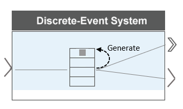
The block is defined as a custom entity generator block that generates entities with specified intergeneration periods. The generated entities carry data, and their priority values are determined by the values of the input signal.
Custom Block Behavior
Define the time between material generations.
    % Nontunable properties
    properties (Nontunable)
        % Generation period
        period = 1;
    end
Initialize the discrete state variables.
    function resetImpl(obj)
        % Initialize / reset discrete-state properties.
        obj.priority = 10;
        obj.value = 1:12;
    end
The variable
priorityrepresents material priority and thevaluerepresents bar code data carried by the materials.Initialize the output for a source block.
    function num = getNumOutputsImpl(~)
        % Define total number of outputs.
        num = 2;
    end
    function [out1 out2] = getOutputSizeImpl(obj)
    % Return size for each output port.
        out1 = [1 12];
        out2 = 1;
    end

    function [out1 out2] = getOutputDataTypeImpl(obj)
        % Return data type for each output port.
        out1 = "double";
        out2 = "double";
    end

    function [out1 out2] = isOutputComplexImpl(obj)
        % Return true for each output port with complex data.
        out1 = false;
        out2 = false;
    end
First function declares the output size.
Second function declares that output port data types are
double.Third function declares
falsefor output ports because they do not support complex data.
Declare the size, data, and complexity of the discrete states.
    function [sz,dt,cp] = getDiscreteStateSpecificationImpl(obj,name)
        % Return size, data type, and complexity of discrete-state.
            switch name
                case 'priority'
                    sz = [1 1];
                case 'value'
                    sz = [1 12];
            end
            dt = "double";
            cp = false;
    end
The discrete state
priorityis scalar. The data type isdoubleand takes real values.The discrete state
valueis a1-by-12vector. The data type isdoubleand takes real values.
Generate the materials with intergeneration period, priority, and data defined by:
The parameter
obj.period, declared as a public parameter that can be changed from the block dialog box.The parameter
obj.priorityvalues, defined by the signal from the input port.The parameter
obj.value, a1-by-12vector which represents the data carried by entities.
    function events = setupEvents(obj)
        % Set up entity generation event for storage 1 at simulation start.
        events = obj.eventGenerate(1,'mygen',obj.period,obj.priority);
        % Set up the initial value of the output signal.
        out1 = 10;
    end

    function [entity,events,out1] = generate(obj,storage,entity,tag,in1)
        % Specify event actions when entity is generated in storage.
        entity.data = obj.value;
        % The value from the signal is assigned to the entity priority.
        obj.priority = in1;
        % Output signal is the assigned priority value.
        out1 = obj.priority;
        events = [obj.eventForward('output',1,0) ...
                    obj.eventGenerate(1,'mygen',obj.period,obj.priority)];
    end
Implement Custom Block
Save the
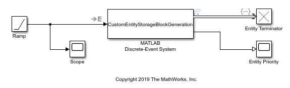
.mfile asCustomEntityStorageBlockGeneration. Link the System object to a SimEvents® model by using a MATLAB Discrete-Event System block. For more information about linking, see Create Custom Blocks Using MATLAB Discrete-Event System Block.Create a SimEvents model that includes the MATLAB Discrete-Event System block, a Ramp block, an Entity Terminator block, and two Scope blocks. Connect the blocks as shown in the model.
In the Ramp block, set Slope to
5and Initial output to10.In the Entity Terminator block, you can display the priority values of the entities arriving at the block, in the Entry action field enter this code.
coder.extrinsic('fprintf');
fprintf('Priority: %d\n', double(entitySys.priority))
Right-click the entity path from the custom Entity Generator to the Entity Terminator and select Log Selected Signals button
 .
.Simulate the model.
Observe the output of the Ramp block. For instance, the output value becomes
15,20,25, and30for the simulation time1,2,3, and4, respectively.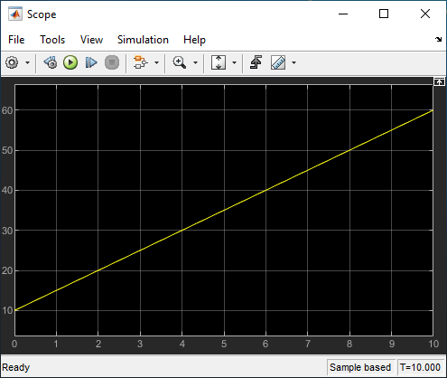
The Simulation Data Inspector shows that entities are forwarded to the Entity Terminator block with data of size 1-by-12.
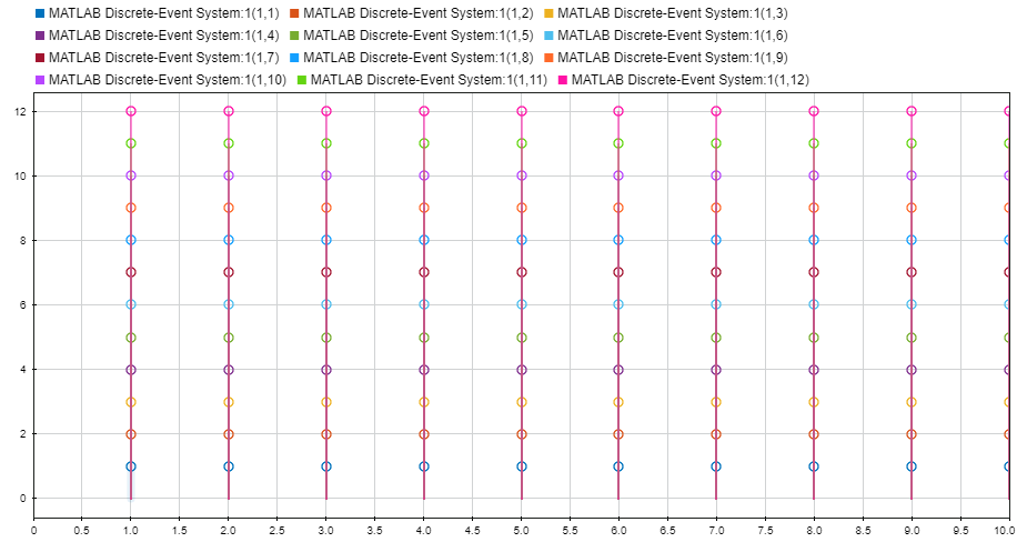
You can also observe the priority values from the scope labeled Entity Priority for generation times
1,2,3,4,5,6,7,8,9, and10.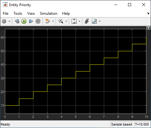
See Also
matlab.DiscreteEventSystem | entry | matlab.System | getEntityStorageImpl | getEntityPortsImpl | generate