Main Content

RF Budget

Simulate RF budget chain of 2-port elements in Idealized Baseband simulation environment

Since R2025a

  • RF budget block icon

Libraries:
RF Blockset / Idealized Baseband

Description

Use the RF Budget block to simulate RF budget results for a chain of 2-port elements in Idealized Baseband simulation environment. While simulating the RF budget, the block accounts for mismatch losses by considering the effects of reflection and bidirectional power flow. You can use the rfbudget object or use the RF Budget Analyzer app as a source for the RF Budget block.

Examples

expand all

This example shows you how to account for mismatch loss between two elements in an RF chain.

To model RF chain you can either:

  • Use the RF Budget block in your model that contains an RF chain.

  • Use the rfbudget object to generate an RF chain. Then, use the exportRFBlockset function to export your model with RF Budget block to account mismatch loss between elements in an RF chain.

This example shows you how to account for mismatch losses using the rfbudget object and export to RF Budget block using the exportRFBlockset function.

To do this:

  • First, define system parameters and construct RF elements.

  • Second, create an rfbudget object to construct an RF chain with the elements that you have designed in the first step and compute its RF budget.

  • Finally, input this rfbudget object to an exportRFBlockset function to export your model with a RF Budget block to account mismatch loss between elements in an RF chain.

Define System Parameters

Define input frequency, signal bandwidth, and input power.

fin = 4e9;
bw = 5e6;
in_dBm = -30;

Create RF Elements

Create an amplifier, n-port device, modulator, and RF filter.

a = amplifier( ...
    Gain = 31, ...
    Zin = 41+15i, ...
    Zout = 92+65i);
s = nport('passive.s2p');
m = modulator( ...
    LO = 1e9, ...
    Gain = 42, ...
    Zin = 35+89i, ...
    Zout = 79+32i);
r = rffilter( ...
    PassbandFrequency = fin+1e9-bw/2, ...
    Zin = 38, ...
    Zout = 38);

Create RF Budget and Construct RF Chain

Create an rfbudget object and calculate its RF budget.

rfobj = rfbudget([a s m r],fin,in_dBm,bw);

Export RF Chain to RF Budget Block

Simulate your RF chain using idealized baseband simulation. This allows you to analyze a cascade of mathematical models of RF components within the MATLAB® environment. Idealized Baseband System objects assume perfect impedance matching. However, by using Mismatch in the exportRFBlockset function, you can account for the mismatch loss between two elements in an RF chain in your simulation.

exportRFBlockset(rfobj,'Library','IdealizedBaseband','Mismatch',true);

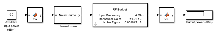
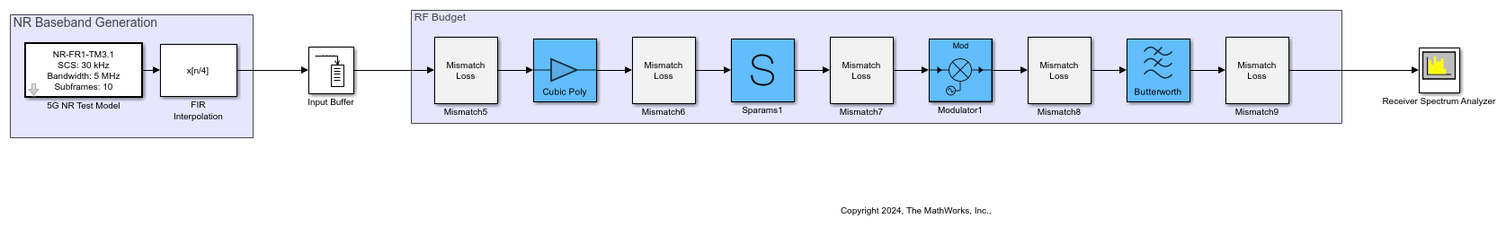
Select the RF Budget block and copy it to a new Simulink® canvas. In the new canvas, click the Edit System button, and then click the Expand System button. Replace the Inport block with a 5G NR baseband input signal. Replace the Outport block with a Spectrum Analyzer block to observe the output.

open_system("mismatch.slx")

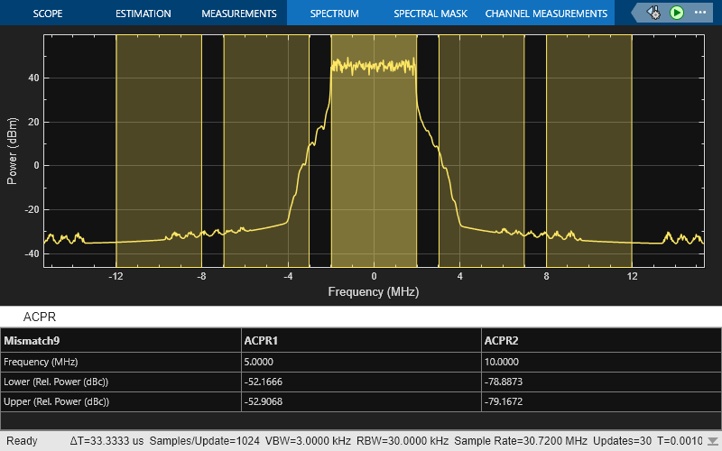
Simulate the system.

sim("mismatch.slx")
ans = 

  Simulink.SimulationOutput:
                   tout: [30721x1 double] 

     SimulationMetadata: [1x1 Simulink.SimulationMetadata] 
           ErrorMessage: [0x0 char] 

Ports

Input

expand all

Time-dependent input signal, specified as a real scalar, real column, complex scalar, or complex column. A column represents consecutive points in time.

Data Types: double | single

Output

expand all

Time-dependent output signal, returned as a complex scalar or complex column. The time-dependent output signal is equal in size to the time-dependent input signal.

Data Types: double | single

Parameters

expand all

To edit block parameters interactively, use the Property Inspector. From the Simulink® Toolstrip, on the Simulation tab, in the Prepare gallery, select Property Inspector.

Main

RF budget source, specified as rfbudget object or RF Budget Analyzer App

Specify an rfbudget object as source to model mismatch loss.

Dependencies

To enable this parameter, set RF budget source to rfbudget object.

Click this button to open the RF Budget Analyzer app to create an RF chain and use it as a source to model mismatch loss. After creating the your RF chain, click the Update Block button to update the RF Budget block with the designed RF chain.

Dependencies

To enable this parameter, set RF budget source to RF Budget Analyzer App.

Select this option to simulate the model using generated C code. The first time you run a simulation, Simulink generates C code for the block. The C code is reused for subsequent simulations as long as the model does not change. This option requires additional startup time, but the speed of the subsequent simulations is faster than interpreted execution simulation.

Click this button to break the RF Budget block's links to the library and replace the variables with values that the block estimates using the block parameters. When clicking this button, the software converts the RF Budget block is either made a simple unmasked subsystem, or gets expanded.

Clicking this button opens a dialog box with these options:

  • Edit System — Edit the internal variables without expanding the subsystem.

  • Expand System — Edit the subsystem and Expand the subsystem in the Simulink canvas. The block will expand into a chain of elements.

    Note

    Mismatch loss will not computed between two elements if the elements are unidirectional and perfectly matched.

  • Cancel — Cancel the operation.

Note

You cannot undo the operation once you click the Edit System or Expand System button.

Advanced

Frequency resolution at which the block models the mismatch loss, specified as a positive scalar. You can:

  • Increase the frequency resolution if your input signal is fast varying.

  • Decrease the frequency resolution if your input signal is slow varying. This option decreases the computation time.

  • Set the frequency resolution to 1 if your input signal is constant.

Bandwidth at which mismatch loss is modeled, specified as a positive scalar. You can

  • Increase the modeling bandwidth if your input signal bandwidth is wider.

  • Decrease the modeling bandwidth if your input signal bandwidth is narrower. In this case, you can decrease the frequency resolution as well to reduce the computation time.

Extended Capabilities

expand all

C/C++ Code Generation
Generate C and C++ code using Simulink® Coder™.

Version History

Introduced in R2025a

See Also