Hybrid Pulse Power Characterization (HPPC) Parameter Estimation
Simscape™ Battery™ includes objects and functions for performing parameter estimation of a battery equivalent circuit model (ECM) from battery hybrid pulse power characterization (HPPC) data. This functionality allows you to process and tabulate battery cell test data, fit or regress parameters for ECMs, verify the accuracy of the fit, visualize parameters trends, and automatically parameterize Simscape Battery cell blocks. HPPC is a valuable technique in the battery industry and is one of the most common battery tests performed both at single-cell level and at system level.
Simscape
Battery contains foundational optimization methods for estimating ECM parameters. You
can also select methods from other toolboxes, such as the tfest
function from the System Identification Toolbox™. These alternative optimization methods often provide more robust parameter
estimation methodologies than the default optimization method. To use these optimization
methods, you must have a license for the required toolbox.
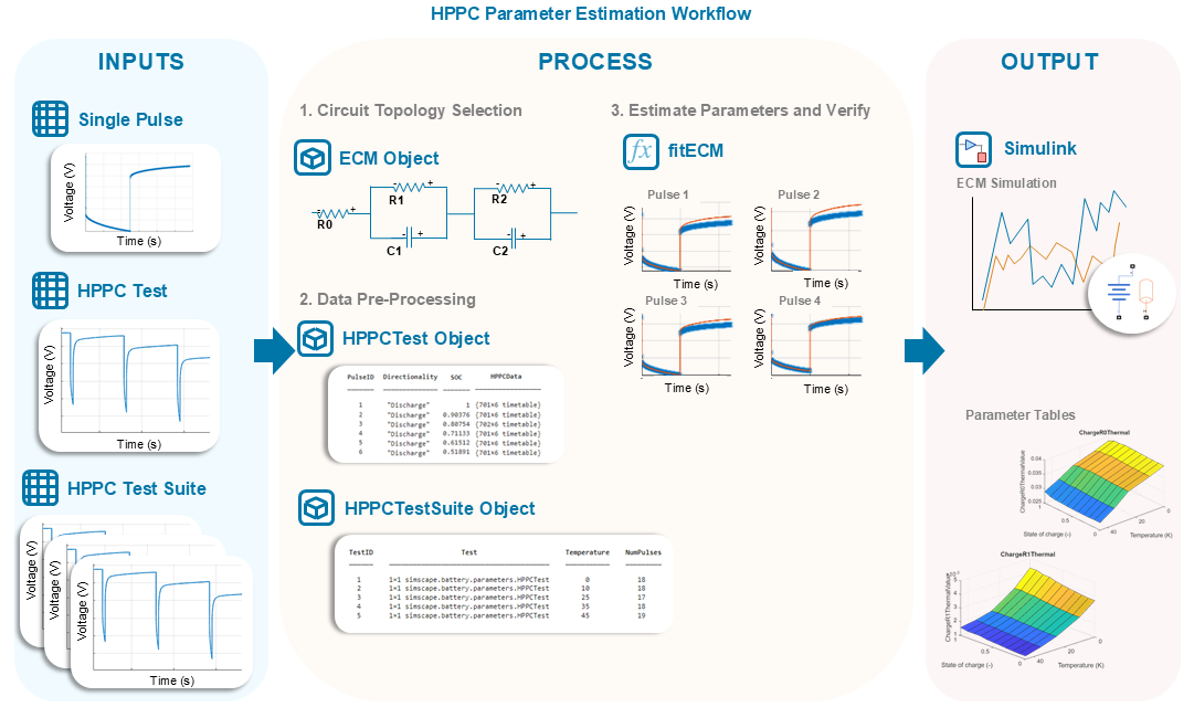
This figure shows the general workflow to estimate model parameters from HPPC data.
Hybrid Pulse Power Characterization
The HPPC technique involves applying a series of constant current pulses to a battery and measuring its terminal voltage and temperature responses at different operating conditions. Multiple key operating conditions affect the impedance of the cell and the measured voltage response. These operating conditions include:
Initial battery soak temperature
Initial state of charge (SOC)
Current or load
Current directionality such as charge or discharge
State of health (SOH) or remaining capacity
Load frequency
Thermal boundary conditions
The measured voltage response from each current pulse contains valuable information about the impedance of the battery. In turn, this impedance gives you information about the battery performance and power capability.
The HPPC test method is essential for characterizing the direct current internal resistance (DCIR) of a battery, developing dynamic battery models, testing and improving the robustness of battery management systems (BMS), and ensuring that batteries meet the performance requirements of their applications. Several organizations have developed standardized HPPC test procedures to ensure consistency and comparability of the results. These are some of the key industry standards:
USABC (United States Advanced Battery Consortium)
IEC 62660-1 (International Electrotechnical Commission)
SAE J1798 (Society of Automotive Engineers)
ISO 12405-1 (International Organization for Standardization)
Idaho National Lab INL/EXT-15-34184
The typical goal for many of these standards is to obtain an approximation of the maximum current and power that a battery can deliver or accept at a given SOC value or at any of the key operating conditions. This plot shows the dynamic voltage response for lithium-ion batteries from an initial resting state or equilibrium state at mild operating conditions of 25°C and 90% SOC.

The measured voltage response in this plot behaves linearly. You can model this response with a low error by using a simple RC-branch equivalent circuit model, such as a 2-RC ECM. However, at colder battery temperatures or at very low SOC conditions, such as when the SOC is less than 10%, the voltage response of a battery can show nonlinear behaviour. In these cases, the estimation algorithm for a linear RC-branch ECM typically fails or provides parameters for models with very low correlations between the measured and simulated battery voltage. You must understand the limitations of the battery models you use and the errors you obtain from the parameter estimation methodology. Extreme operating conditions are best modeled by using electrochemical battery models or physics-enhanced equivalent circuit models, instead of linear ECMs.

In Simscape Battery, you can use HPPC data to derive or estimate the parameters for a linear RC-branch ECM across different temperatures, SOC values, and currents. You can then use the estimated parameters to parameterize a Battery Equivalent Circuit block.
Select Circuit Topology
To ensure that your model is computationally efficient, captures the necessary dynamics, and matches the goals of your analysis or application, you must appropriately select the model circuit topology according to the test data you want to use. The topology determines the complexity of the model, balancing between computational efficiency and accuracy. More complex topologies capture more detailed behaviors but require you to estimate more parameters.
To estimate the parameters for a battery ECM, use the ECM object. The
ECM object creates an equivalent circuit model object for
estimating the battery parameters from impedance data. Use this object when you perform
HPPC tests to collect your data.
ECMs approximate the dynamic behavior of an electrochemical cell, such as the voltage response over time, by using a collection of electrical circuit elements, including resistors, capacitors, and inductors connected in a specific circuit topology. An ECM is an analogy to a real electrochemical system. ECMs have faster simulation times but lower model fidelity and accuracy.
This table shows the most typical ECMs used to represent the impedance of a battery.
| Circuit Name | NumRCPairs Property Value | Topology and Parameters |
|---|---|---|
| Single resistor | 0 |
|
| Thevenin ECM or 1-RC branch ECM | 1 |
|
| 2-RC branch ECM | 2 |
|
| 3-RC branch ECM | 3 |
|


For more information about the ECM object and its properties and
functions, see ecm.
Process Test Data
To import, view, process, and store data from both HPPC experimental techniques in
Simscape
Battery, use the HPPCTest and HPPCTestSuite
objects.
HPPCTest Object
The HPPCTest object allows you to visualize, tabulate, and
manipulate the different constant current pulses inside your HPPC data. The
HPPCTest object contains a summary of all the current pulses
performed in a single HPPC test program. This object automatically identifies each
constant current pulse and tabulates it for inspection and preparation for the
parameter estimation process as an optional data pre-processing step. This HPPC test
data must be in a MAT file format and must contain time, current,
and voltage signals. Optionally, you can specify the temperature, charge, and
SOC.
By using the object functions of the HPPCTest object, you can
plot the entire HPPC test voltage or the measured voltage for a specific pulse, add
or remove data of a current pulse, and update the SOC values for all charge or
discharge pulses at once.
The HPPCTest object automatically identifies the charge and
discharge constant current pulses from the data according to these
properties:
ValidPulseDurationRange— Valid pulse duration range that indicates whether a pulse is valid and must be stored in theTestSummaryproperty table. Decreasing the upper bound to values lower than 60 seconds ensures that very long discharges, such as capacity checks, are not included in the final list of pulses for estimation. Increasing the lower bound for this property to values greater than one or two seconds ensures that the function excludes potential noise, outlier currents, or abnormally short pulses from the final list of pulses for estimation.ValidVoltageRange— Valid battery voltage range that indicates whether a pulse is valid and must be stored in theTestSummaryproperty table.CurrentOnThreshold— Threshold current value that indicates whether a charge or a discharge is occurring. This value is important for experiments where the rest or baseline current is not equal to zero.NumSamplesRequirement— Number of sequential points, specified as a scalar, at which the current must be greater than the value of theCurrentOnThresholdproperty to signify the presence of a charge or discharge pulse.
You can customize these properties with your individual options to filter out or only select the pulses that you want to use for parameter estimation.
For more information about the object and its properties and functions, see
hppcTest.
HPPCTestSuite Object
You can perform battery HPPC testing at many different conditions, including temperature, SOC, current, and remaining capacity. You can then store these tests in more than one file. Simscape Battery refers to several HPPC test files as an HPPC test suite. HPPC test suites are typically categorized depending on the battery temperature at the start of each current pulse, which remains constant across different SOC values and load currents. In other cases, the initial temperature of the battery can also vary inside a given test file depending on the test settings and thermal environment.
In Simscape
Battery, you can estimate multidimensional parameter tables for a suite of
HPPC tests by merging different battery ECM objects or by using an
HPPCTestSuite object. An HPPCTestSuite object
is a collection of different separate HPPC tests that you normally conduct at
different temperatures, for different cells, or at different battery C-rates. You
can optionally define a temperature for each HPPC test.
For more information about the object and its properties and functions, see
hppcTestSuite.
Estimate Model Parameters
After you choose the equivalent circuit model topology that reflects your battery behavior, you use the collected HPPC test data to fit the model. This process involves adjusting the model parameters to minimize the difference between the model predictions and the experimental data. To find the best-fit parameters, you use optimization algorithms. You then validate the model by comparing the predictions against additional experimental data or different operating conditions to ensure accuracy and reliability.
For HPPC data, the process of parameter estimation involves minimizing the error
between the predicted voltage output of the ECM and the measured battery voltage
response from the HPPC test. To minimize the error, you iteratively adjust the model
parameters, such as R0, R1, and
C1, until you achieve a satisfactory error between the measured
voltage and a simulated voltage.
The fitECM function performs impedance parameter estimation for a
battery ECM from time-based HPPC data. These parameters are then stored inside an
ECM object that you can use to parameterize a Battery Equivalent
Circuit block.
You can select different fitting methods for estimating the model parameters. To
choose the fitting method and the segment of the pulse to fit, specify the
FittingMethod and SegmentToFit properties,
respectively. This table shows the list of available options for these properties in the
fitECM function. Selecting these methods requires you to have a
license for the associated MATLAB® toolbox.
| Required MATLAB Toolbox | FittingMethod Property | SegmentToFit Property |
|---|---|---|
| Simscape Battery | fminsearch |
|
| Simscape Battery and Curve Fitting Toolbox™ | curvefit |
|
| Simscape Battery and System Identification Toolbox | tfest |
|
| Simscape Battery and Model-Based Calibration Toolbox™ | mbc | Not Available |
The battery ECM parameters for a specific operating point can be different depending
on which segment or section of the current pulse you use for the parameter estimation
process. The load-segment parameters suit most applications. However, the best
estimation segment depends on the specific end application of the battery ECM. Some
methods are better suited to estimate parameters for a given segment. For example, the
tfest function works best for fitting load-only dynamics. The
fminsearch method is very sensitive to initial parameter
values, upper parameter bounds, and lower parameter bounds.
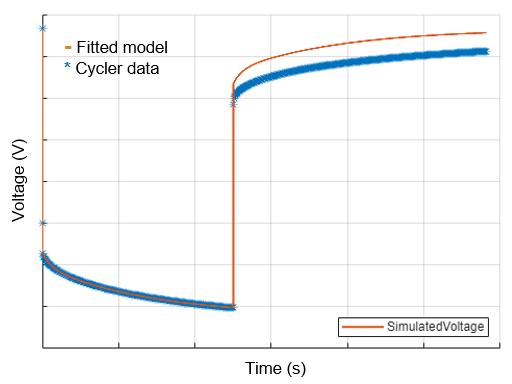
This figure shows the measured and the simulated voltage response of a battery ECM
whose parameters are estimated using the fitECM function. The
function calculates the simulated voltage with a 2-RC model with a constant open-circuit
voltage value.
For more information about the fitECM function and its arguments, see
fitECM.
Ohmic Resistance Calculation
The fitECM function calculates the ECM parameters in
different ways depending on the fitting method that you choose.
For the "fminsearch",
"curvefit", and "tfest"
methods, the function uses the value of the ThresholdForR0 to
directly calculate the ohmic resistance values based on the initial voltage drop of
the constant current pulse. The value of the ThresholdForR0
property represents the time at which the function computes the instantaneous
resistance by applying Ohm's law. In the Ohm's law equation, the current at
ThresholdForR0 is the denominator and the initial voltage
at rest minus the voltage at ThresholdForR0 is the numerator.
The function uses nearest interpolation to estimate both the voltage and the current
values at ThresholdForR0.
This equation calculates the ohmic resistance:
where:
U0— Initial voltage or open-circuit voltage at the start of the pulse, in voltsUThresholdForR0 — Interpolated voltage at theThresholdForR0property value, in voltsIThresholdForR0 — Interpolated current at theThresholdForR0property value, in amperes
Dynamic Resistance Calculation
You can calculate the other higher-order dynamic parameters related to the RC
branches, such as R1, C1,
Tau1, R2, C2,
Tau2, R3, C3, and
Tau3, by using the identification methods or
optimization-based methods for curve and model fitting.
The below figure shows a summary of the key impedance dynamics or overpotentials that occur and evolve over time when a battery is put under load. Initially, during the first milliseconds after the current reaches its designated value, the measured terminal voltage changes mainly due to the ohmic resistance. The ohmic resistance is the resistance associated with the conduction of electricity through a material, and it remains present as long as there is a current that flows through the cell. If the pulse is sustained for tenths of a second and longer, the electrochemical reaction at the interface of the electrodes continues to evolve, requiring a relatively small amount of energy. This energy is required for transferring the lithium from its metallic intercalated state to a solvated ion, or from a solvated ion to its metallic state. This small amount of energy requirement effectively gives rise to an additional charge transfer resistance. This resistance remains active and evolves as long as the current pulse is sustained. Finally, after seconds, the diffusional processes and other mass transport mechanisms that occur inside the battery microstructure also translate into additional resistances that grow with time and current density. So, when you design the HPPC experiment, you must consider the appropriate sampling frequencies. The sampling frequencies determine how well you can capture, decouple, and understand the different dynamics.

The left plot shows the measured voltage response of a battery to a constant current pulse. The voltage is measured as a function of time or pulse duration. The right plot shows the absolute value of the real impedance that you obtain by using the electrochemical impedance spectroscopy (EIS) technique. The resistance values from both techniques must match for a given set of conditions. EIS is a better technique to understand the timescales at which the different overpotentials occur within a battery. You can use EIS to understand the timescale at which the ohmic resistance occurs and how to sample to decouple the ohmic and charge transfer contributions.
Parameterize and Simulate
The final step in the parameter estimation workflow depends on whether you used HPPC or EIS data to estimate your model parameters.
For HPPC data, you can the estimated parameters to parameterize a Battery Equivalent
Circuit block. This parameterization allows you to run battery
simulations in Simulink®. To parameterize a Battery Equivalent Circuit block, use the parameterizeEquivalentCircuitBlock function of the ECM
object.
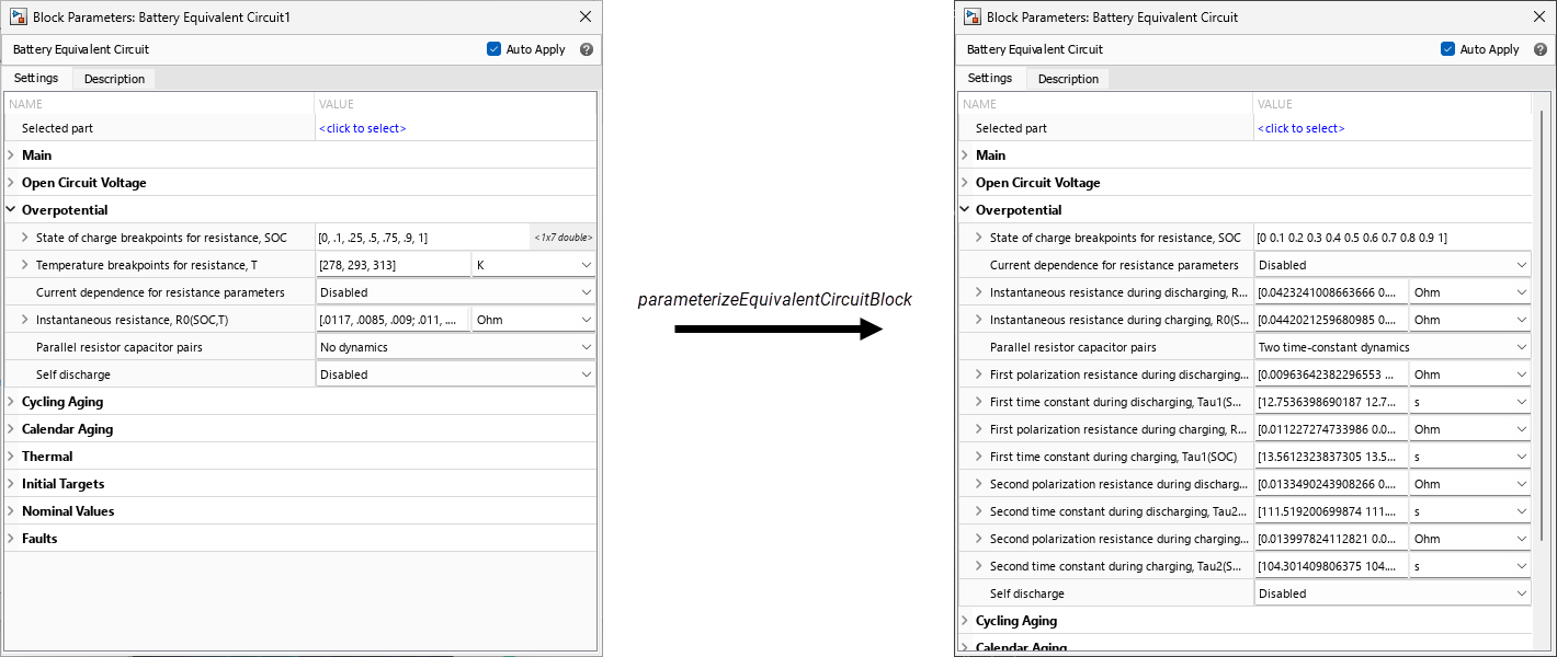
This figure shows the parameters inside the Battery Equivalent Circuit block mask
before and after the parameterization. The block mask on the left shows the default
values for the parameters of the Battery Equivalent Circuit block. When you call the
parameterizeEquivalentCircuitBlock function, the software
automatically parameterizes the model parameters with the estimated values inside the
ECM object.
References
[1] Barai, Anup, Kotub Uddin, W. D. Widanage, Andrew McGordon, and Paul Jennings. “A Study of the Influence of Measurement Timescale on Internal Resistance Characterisation Methodologies for Lithium-Ion Cells.” Scientific Reports 8, no. 1 (January 8, 2018): 21. https://doi.org/10.1038/s41598-017-18424-5.
See Also
hppcTest | hppcTestSuite | ecm | fitECM | Battery Equivalent
Circuit | parameterizeEquivalentCircuitBlock