Configure and Calibrate Pan Tilt Hardware Using Raspberry Pi Pan Tilt HAT
This example shows how to configure and calibrate the pan and tilt hardware using the Pan Tilt HAT block from Simulink® Support Package for Raspberry Pi® Hardware.
Prerequisites
For more information on how to use the Simulink Support Package for Raspberry Pi Hardware, see Get Started with Simulink Support Package for Raspberry Pi Hardware.
Activate and load the PCA9685 kernel module on your Raspberry Pi hardware board before using the Pan Tilt HAT block from the support package. For more information, see Activate, Load, and Verify PCA9685 Kernel Module.
Required Hardware
Raspberry Pi board
Power supply with at least 1A output
Pan Tilt HAT hardware module
Camera board
Hardware Setup
Mount the Pan Tilt HAT hardware module on your Raspberry Pi board.
Mount the camera board to your pan and tilt hardware module.
Connect the CSI cable of the camera board to the CSI port on the Raspberry Pi. For more information, refer to Camera Module.
Configure Simulink Model and Calibrate Parameters
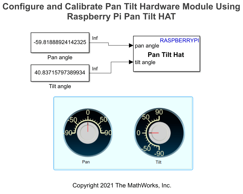
Open the raspberrypi_pantilthat_gettingstarted Simulink model.

Panning angles vary from –90 to 90 degrees, –90 degrees to move the camera to the extreme left. Similarly, tilting angles vary from –90 to 90 degrees, –90 degrees to tilt the camera all the way up. For precise position control of the pan and tilt servos, for a constant pulse width modulation (PWM) frequency, you must calibrate the minimum and maximum pulse duration to find the extreme positions of these servos.
Use the Pulse duration [min max] parameter in the Pan and Tilt Servo sections of the Pan Tilt Hat Block Parameters dialog box to calibrate the pan and tilt angles from –90 to 90 degrees. Adjust the PWM frequency to determine how many full pulses per sample are generated by the PCA9685 PWM kernel. Increase the PWM frequency to obtain a smoother movement of the pan and tilt hardware module. Note that once you set the PWM frequency, you need to recalibrate the minimum and maximum pulse durations of the pan and tilt servos.
Run Simulink Model in Connected IO Mode
Open the Pan Tilt Hat Block Parameters dialog box.
Set a frequency in the PWM frequency parameter. For example,
50Hz.To pan your hardware to –90 degrees, set a minimum value in the Pulse duration [min max] parameter in the Pan Servo section.
On the Hardware tab of the Simulink model, in the Mode section, select Run on board and then select
Connected IOfrom the drop-down list. In the Run on Computer section, click Run with IO.Change the pan values using the Dashboard Knob on the interactive dashboard display. Observe and check if the pan and tilt hardware module has reached its extreme left or not. Keep changing the minimum in the Pulse duration [min max] parameter until the hardware reaches its extreme left. To avoid overloading the PCA-9685 PWM I2C driver, do not rigorously move the knob on the display. Change the pan value and let the hardware module settle to this change. Only after the hardware module settles, make the next change in the pan angles using the knobs.
To pan your hardware at 90 degrees, do not change the value set in the PWM frequency parameter. Repeat steps 2–5 while setting the maximum value in the Pulse duration [min max] parameter in the Pan Servo section.
Repeat steps 2–5 to tilt your hardware from –90 to 90 degrees. Use the PWM frequency and Pulse duration [min max] parameters in the Tilt Servo section.
Deploy Simulink Model on Raspberry Pi Hardware
In the Configuration Parameters dialog box, select Hardware Implementation from the left pane and set Hardware board to
Raspberry Pi.In the Target hardware resources section, select Dashboard properties.
Select Enable deployment for Dashboard blocks.
Click Apply and then OK.
On the Hardware tab of the Simulink model, in the Mode section, click Run on board and then select
Run on boardfrom the drop-down list. In the Deploy section, click Build, Deploy & Start. To view the dashboard panel on the Raspberry Pi, open a VNC session or connect a display to Raspberry Pi.If you have Embedded Coder® already installed, after you deploy the model on your Raspberry Pi, click View diagnostics to open the Diagnostic Viewer dialog box window below the Simulink model.
Click the index.html link to open the dashboard panel in a web browser after the model is successfully deployed on your Raspberry Pi hardware. To view the dashboard on a web browser of any external device, connect your Raspberry Pi and external device to the same network. Using the knobs on the dashboard, you can now control the pan and tilt angles on the hardware.
Other Things to Try
After you calibrate the pan and tilt angles of the pan and tilt hardware module, try these examples:
See Also
Get Started with Deploying Web-Based Customizable Dashboard Blocks on Raspberry Pi