Battery Management System Design
Best Practices for Interface and Data Management
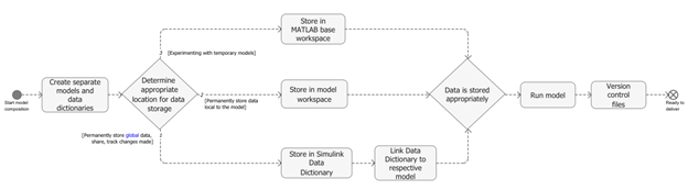
When using componentization or model referencing, in collaborative Model-Based Design, you must choose the appropriate location to store model data based on the use case:
For experimenting with temporary models, store data in the MATLAB® base workspace.
For permanently storing data that is local to the model, store data in the model workspace.
For permanently storing global data, sharing data between models, and tracking changes made to data, store data in a Simulink® data dictionary.
This flow chart illustrates the ideal workflow for interface and data management.
To help manage data when building a large composite model from scratch, follow best practices by describing the implementation at each level of the model. For more information, see Store Shared Data in Architectural Data Section.
Componentized data management supports:
Componentized development
Developing components or subcomponents independently, without starting from the system model and without the rest of the system files being available
Easy data sharing without excessive linkage between components
Checking consistency of duplicate data definitions
Scoping data to the system and specific level of system hierarchy
The BMS consists of a controller and a plant model. Follow these steps to develop a BMS plant model and a BMS controller model.
BMS Design
In the BMS model, the architecture acts as the high-level design while the Simulink model functions as the low-level or unit design. The BMS controller includes these subsystems:
Current and Power Limit CalculationState Of Charge (SOC) EstimationCharge ManagementState MachinePassive Cell BalancingContactor ManagementFault Detection
Design of BMS Controller Model
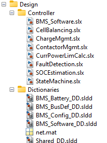
Develop separate Simulink models for the subsystems and include the associated Simulink data dictionary.
Use the model workspace or the MATLAB base workspace based on the use case. For guidance on choosing data storage locations, see Best Practices for Interface and Data Management.
Add any custom model reference configurations to the project.
Check that the correct set of reference configurations to the project.
Use libraries, subsystem, and model reference to meet your modeling needs. For more information, see Best Practices for Model Composition and Components.
The battery model of the BMS uses subsystem references. The charger and drive load models are separate subsystems that are referenced in the main model.
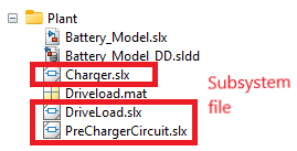
You can develop subsystems independently as part of componentization and then integrate them at the end.
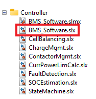
Open the BMS controller model.
open('BMS_Software.slx');
sim("BMS_Software.slx");
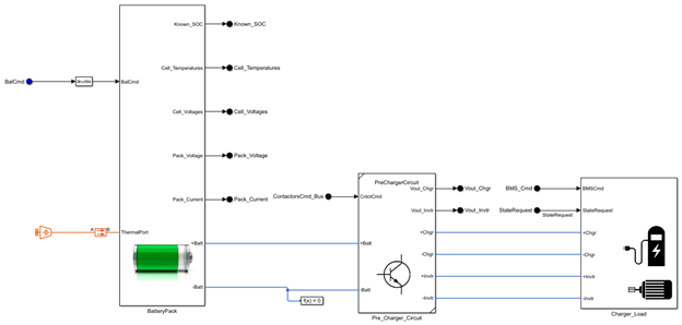
Design of Battery Plant Model
The plant model uses a Simscape™ battery model. The battery model consists of 12s3p cells, with
three cells arranged in parallel and 12 cells arranged in series. To create a
battery pack, refer to BatteryPackDesignScript.mlx or use the
Battery
Builder (Simscape Battery) app.

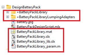
To design a custom battery pack, modify the
BatteryPackDesignScript.mlxfile according to the required cell configuration.The highlighted files will be available after you execute the battery pack design script.
The figure shows the generated Simscape battery model.
See Also
Topics
- What Is a Data Dictionary?
- Battery Modeling Workflow (Simscape Battery)