Use Scenarios and Insert Signals in Signal Editor
Use Scenarios to Group and Organize Inputs
Signal Editor uses scenarios to group and organize sets of inputs to be saved to a MAT-file for a single simulation. To create signal data using existing data sets from existing scenarios, or create an empty scenario into which to add signals, use the Signal Editor Scenario menu.

| Action | Option |
|---|---|
To create a scenario from the root inports of a model | Select Scenario > Scenario from Model. (Available only when accessing Signal Editor from the Root Inport Mapper.) You can also use the Note When using this option, the resulting scenario contains signals with the data types and dimensions of the inport ports. |
To create an empty scenario and create signals from scratch | Select Scenario > Scenario. |
To import scenarios from MATLAB® workspace | Select Scenario > From Workspace. |
After you have your scenario:
To begin inserting signals, use options in the Insert section. For more information, see Create Signals and Signal Data.
To change the signal order in the hierarchy or change the name of a signal, see Change Signal Names and Hierarchy Orders.
Link in Signal Data from Signal Builder Block and Simulink Design Verifier Environment
You can use Signals > Edit MAT-File to link in MAT-file data from these sources for editing.
Signal Builder blocks.
Simulink® Design Verifier™.
Link in Data from Signal Builder
You can link in and edit data exported from the Signal Builder block in a MAT-file or MATLAB. Use one of these methods to export the data:
Signal Builder block File > Export Data > To MAT-file option, then link in the MAT-file.
signalbuilder getfunction with data sets, then perform either of these steps:Import the data sets in the workspace and save to a MAT-file
Save the data sets in the workspace to a MAT-file and import the MAT-file
For more information on exporting from a Signal Builder block, see Exporting Signal Group Data.
Link in Test Vectors from Simulink Design Verifier Environment
You can link in and edit Simulink Design Verifier test vectors. This workflow requires a Simulink Design Verifier license.
Before linking in, use the Simulink
Design Verifier sldvsimdata (Simulink Design Verifier)Simulink.SimulationData.Dataset objects. This file contains a test vector structure sldvData. Save the output to a MAT-file and then import that file into Signal Editor.
Insert Signals
To insert signals into scenarios, select the scenario. Then, from the Insert section, select a signal.
The new signals appear in the Inputs section.
You can also insert multiple signals of the same type. For more information, see Create Signals with the Same Properties.
To change the signal order in the hierarchy or change the name of a signal, see Change Signal Names and Hierarchy Orders.
To edit the properties of a signal:
For tabular editing, see Work with Basic Signal Data.
To replace the signal data or edit the signal notation using MATLAB expressions, see Replace Signal Data with MATLAB Expressions.
Add Signals to Scenarios
This example describes how to create a scenario to be linked to from the Root Inport Mapper tool. You can then start the Signal Editor to manipulate and add signals to this scenario.
In the MATLAB Command Window, create some data by typing:
ts = timeseries([0;20],[0;10]);
In Simulink Editor, create a model that contains three Inport blocks, three Gain blocks, a Mux block, and a Scope block. Connect these blocks as shown:
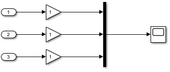
Set the gain for the Gain blocks to
5,10, and15, respectively.Click one of the Inport blocks, then in the Simulink Editor toolstrip, click the Root Inport > Connect Inputs button.
The Root Inport Mapper tool displays.
In Root Inport Mapper Link section, select From Workspace.
In the From Workspace window, select ts and click OK. In the Save As dialog, enter a name to store the MAT-file, then click OK.
In the Edit section of the Root Inport Mapper, select Signals > Edit MAT-File.
In the Selected Linked MAT-File window, select the new MAT-file and click OK.
The Signal Editor displays with scenario whose name is the same as the MAT-file.
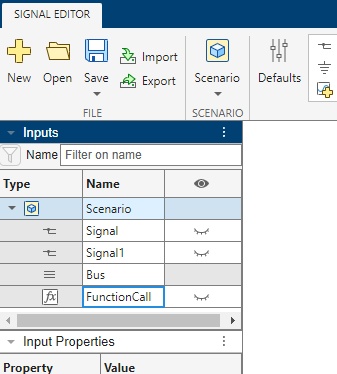
Add a new scenario. Click Scenario.
Add a signal,
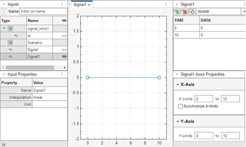
Signal, to the scenario. Right-click the scenario and select Insert > Signal.This action adds
Signalwith these default properties.
Alternatively, insert signals by clicking a signal type from the Insert section or using the Signal split button to author a signal using signal notations.
Change the default properties of signals you want to add. In the Insert section, select Defaults. In the Default Properties for Insertion dialog box, change the data type to
boolean, then right-click the scenario and select Insert > Signal.This action adds Signal1 with the data type
boolean.To check that the data type is
boolean, -double-click for Signal1.