Coordinate Systems in Simulink 3D Animation
Simulink®
3D Animation™ uses these coordinate systems for actor transformation in the 3D environment.
Use the CoordinateSystem argument or property in the
sim3d actor objects or the Coordinate system
parameter in the Simulation 3D blocks to set the coordinate system of the
actor.
| Coordinate System | Object or Block Setting | Description | |
|---|---|---|---|
| World coordinate system | Default | The world uses the Unreal Engine® coordinate system. The Unreal Engine coordinate system is a left-handed Cartesian coordinate system, in m and rad. Axes
Rotation
|
|
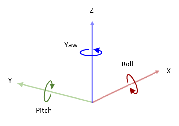
| MATLAB® coordinate system | MATLAB | The MATLAB coordinate system is a right-handed Cartesian coordinate system with Z-up orientation, in m and rad. Axes
Rotation
|
|
| ISO 8855 standard coordinate system | ISO8855 | The ISO 8855 standard coordinate system is a right-handed Cartesian coordinate system with Z-up orientation, in m and deg. This coordinate system is defined in the ISO 8855[2] standard. Axes
Rotation
|
|
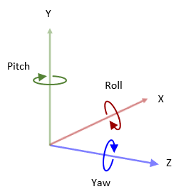
| X3D ISO standard coordinate system | VRML | The X3D ISO standard coordinate system is a right-handed Cartesian coordinate system with Y-up orientation, in m and rad. Axes
Rotation
|
|
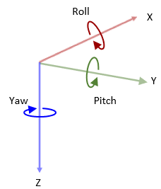
| SAE coordinate system | SAE or AERO | The SAE J670 standard coordinate system is a right-handed Cartesian coordinate system with Z-down orientation, in m and rad. This is defined in the SAE J670[1] standard. This coordinate system is used for aerospace applications. For more information, see Body Coordinates (Aerospace Blockset). Axes
Rotation
|
|
For an example on how the coordinate system specifies the actor transformations in the 3D environment, see View Actor Orientation in MATLAB Coordinate System.
References
[1] Vehicle Dynamics Standards Committee. Vehicle Dynamics Terminology. SAE J670. Warrendale, PA: Society of Automotive Engineers, 2008.
[2] Technical Committee. Road vehicles — Vehicle Dynamics and Road-Holding Ability — Vocabulary. ISO 8855:2011. Geneva, Switzerland: International Organization for Standardization, 2011.
See Also
Topics
- View Actor Orientation in MATLAB Coordinate System
- Create 3D Simulations in Unreal Engine Environment
- Interact with 3D Simulation Environment


