Create and Configure slTuner Interface to Simulink Model
This example shows how to create and configure an slTuner interface for a Simulink® model. The slTuner interface parameterizes blocks in your model that you designate as tunable and allows you to tune them using systune. The slTuner interface generates a linearization of your Simulink model, and also allows you to extract linearized system responses for analysis and validation of the tuned control system.
For this example, create and configure an slTuner interface for tuning the Simulink model rct_helico, a multiloop controller for a rotorcraft. Open the model.
open_system('rct_helico');
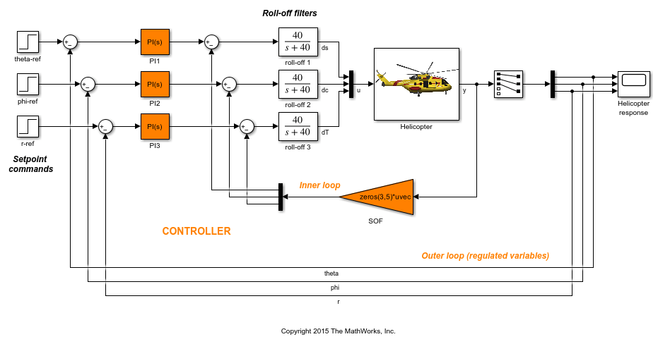
The control system consists of two feedback loops. The inner loop (static output feedback) provides stability augmentation and decoupling. The outer loop (PI controllers) provides the desired setpoint tracking performance.
Suppose that you want to tune this model to meet the following control objectives:
Track setpoint changes in
theta,phi, andrwith zero steady-state error, specified rise times, minimal overshoot, and minimal cross-coupling.Limit the control bandwidth to guard against neglected high-frequency rotor dynamics and measurement noise.
Provide strong multivariable gain and phase margins (robustness to simultaneous gain/phase variations at the plant inputs and outputs).
The systune command can jointly tune the controller blocks SOF and the PI controllers to meet these design requirements. The slTuner interface sets up this tuning task.
Create the slTuner interface.
ST0 = slTuner('rct_helico',{'PI1','PI2','PI3','SOF'});
This command initializes the slTuner interface with the three PI controllers and the SOF block designated as tunable. Each tunable block is automatically parameterized according to its type and initialized with its value in the Simulink model.
To configure the slTuner interface, designate as analysis points any signal locations of relevance to your design requirements. First, add the outputs and reference inputs for the tracking requirements.
addPoint(ST0,{'theta-ref','theta','phi-ref','phi','r-ref','r'});
When you create a TuningGoal.Tracking object that captures the tracking requirement, this object references the same signals.
Configure the slTuner interface for the stability margin requirements. Designate as analysis points the plant inputs and outputs (control and measurement signals) where the stability margins are measured.
addPoint(ST0,{'u','y'});
Display a summary of the slTuner interface configuration in the command window.
ST0
slTuner tuning interface for "rct_helico":

4 Tuned blocks: (Read-only TunedBlocks property)
--------------------------
Block 1: rct_helico/PI1
Block 2: rct_helico/PI2
Block 3: rct_helico/PI3
Block 4: rct_helico/SOF

8 Analysis points:
--------------------------
Point 1: 'Output Port 1' of rct_helico/theta-ref
Point 2: Signal "theta", located at 'Output Port 1' of rct_helico/Demux1
Point 3: 'Output Port 1' of rct_helico/phi-ref
Point 4: Signal "phi", located at 'Output Port 2' of rct_helico/Demux1
Point 5: 'Output Port 1' of rct_helico/r-ref
Point 6: Signal "r", located at 'Output Port 3' of rct_helico/Demux1
Point 7: Signal "u", located at 'Output Port 1' of rct_helico/Mux3
Point 8: Signal "y", located at 'Output Port 1' of rct_helico/Helicopter

No permanent openings. Use the addOpening command to add new permanent openings.
Properties with dot notation get/set access:
      Parameters         : []
      OperatingPoints    : [] (model initial condition will be used.)
      BlockSubstitutions : []
      Options            : [1x1 linearize.SlTunerOptions]
      Ts                 : 0
In the command window, click any highlighted signal to see its location in the Simulink model.
In addition to specifying design requirements, you can use analysis points for extracting system responses. For example, extract and plot the step responses between the reference signals and 'theta', 'phi', and 'r'.
T0 = getIOTransfer(ST0,{'theta-ref','phi-ref','r-ref'},{'theta','phi','r'});
stepplot(T0,1)

All the step responses are unstable, including the cross-couplings, because this model has not yet been tuned.
After you tune the model, you can similarly use the designated analysis points to extract system responses for validating the tuned system. If you want to examine system responses at locations that are not needed to specify design requirements, add these locations to the slTuner interface as well. For example, plot the sensitivity function measured at the output of the block roll-off 2.
addPoint(ST0,'dc')
dcS0 = getSensitivity(ST0,'dc');
bodeplot(dcS0)

Suppose you want to change the parameterization of tunable blocks in the slTuner interface. For example, suppose that after tuning the model, you want to test whether changing from PI to PID controllers yields improved results. Change the parameterization of the three PI controllers to PID controllers.
PID0 = pid(0,0.001,0.001,.01);  % initial value for PID controllers
PID1 = tunablePID('C1',PID0);
PID2 = tunablePID('C2',PID0);
PID3 = tunablePID('C3',PID0);

setBlockParam(ST0,'PI1',PID1,'PI2',PID2,'PI3',PID3);
After you configure the slTuner interface to your Simulink model, you can create tuning goals and tune the model using systune or looptune.
See Also
slTuner | addBlock | addPoint | setBlockParam | getIOTransfer | getSensitivity