Rilevamento degli errori di progettazione in un modello
L'analisi di rilevamento degli errori di progettazione determina le condizioni che causano gli errori rilevati utilizzando Simulink® Design Verifier™. L'analisi di rilevamento degli errori di progettazione calcola inoltre un intervallo di valori del segnale che possono verificarsi per le porte di output del blocco e per i dati locali di Stateflow® nel modello.

Per analizzare il modello e individuare eventuali errori di progettazione:
Verificare che il modello sia compatibile con il software Simulink Design Verifier. Specificare le impostazioni del modello che controllano come Simulink Design Verifier rileva errori di progettazione nel modello.
Utilizzare Defect Checker per rilevare errori di progettazione comuni nel modello.
Eseguire l'analisi di rilevamento degli errori di progettazione per gli errori selezionati.
Al termine dell'analisi, rivedere i risultati.
Fare clic sui singoli blocchi per visualizzare i risultati dell'analisi relativi a quel blocco.
Creare un modello harness contenente casi di test che dimostrino gli errori.
Creare un report di analisi che contenga i risultati dettagliati per l'intero modello.
Correggere gli errori di progettazione individuati durante l'analisi.
Modello di esempio
Questo tutorial utilizza un modello di controller sldvexDetectDesignErrorsExample che ha tre input di sensori: SensorA, SensorB e SensorC. In questo tutorial, si esegue l'analisi di rilevamento degli errori di progettazione per gli errori di overflow di interi e divisione per zero nel modello.
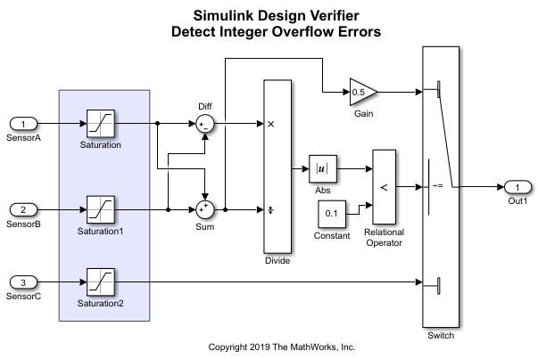
Simulink Design Verifier identifica i costrutti del modello che possono causare overflow di interi, quindi dimostra che l'overflow di interi non può verificarsi durante la simulazione oppure genera casi di test che dimostrano l'errore di overflow di interi. L'algoritmo del controller genera l'output in base ai valori di SensorA e SensorB:

Il modello sldvexDetectDesignErrorsExample incorpora questo algoritmo utilizzando i blocchi Simulink.
In questo tutorial, si imparerà a:
Preparare il modello per l'analisi di rilevamento degli errori di progettazione e verificare la compatibilità del modello.
Utilizzare Defect Checker per rilevare i difetti nel modello.
Eseguire l'analisi di rilevamento degli errori di progettazione sul modello.
Visualizzare i risultati facendo clic sui componenti del modello evidenziati oppure creando un harness o un report di analisi.
Correggere gli errori di progettazione individuati.
Per come iniziare con questo tutorial, vedere Preparazione del modello per l'analisi di rilevamento degli errori di progettazione.