Update Existing Test Cases When Model Interface Changes
R2026bAssume you have already generated test cases by using Simulink® Design Verifier™ for your model. After the analysis completes, you change or modify the model interface by changing the input signals or their properties. This invalidates the existing test cases and you have to update these test cases.
This example shows how to adapt existing generated test cases to the new interface when the model interface changes.
View Existing Test Cases for Cruise Controller
The model crs_controller_basic represents an automotive cruise control system. It receives two categories input of signals: commands from the driver's dashboard button and data from vehicle sensors. The cruise controller sends status indication signals and throttle control commands.
Open the cruise controller model:
model = "crs_controller_basic";
open_system(model);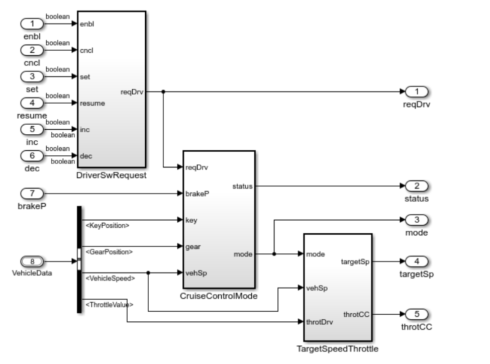
To view the Simulink Design Verifier report for the results stored in crs_controller_basic_sldvdata.mat:
sldvreport("crs_controller_basic_sldvdata.mat");Enhance the Cruise Controller Model
An Adaptive cruise control (ACC) system maintains a safe distance (as shown in the image) from the lead vehicle and keeps the host vehicle within a set speed limit by using a long-range radar (LRR) to estimate the distance.
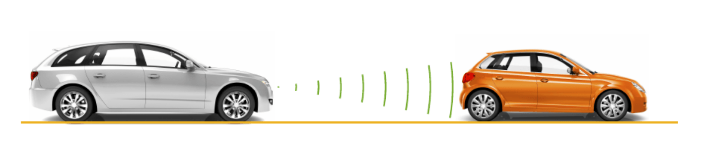
Assume you want to enhance the crs_controller_basic model into an ACC system.
First, add a field named RelativeDistance to the VehicleData bus to record the distance from the leading vehicle. See the image.
The updated definition for the VehicleData bus is:
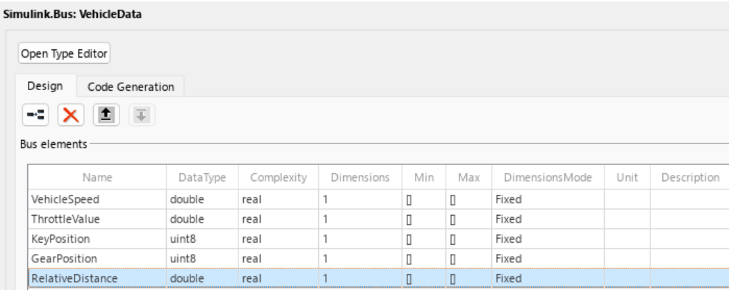
In this example, use the model crs_controller_adaptive for ACC. Check the Bus Selector block to confirm the presence of the RelativeDistance field.
updatedModel = "crs_controller_adaptive";
open_system(updatedModel);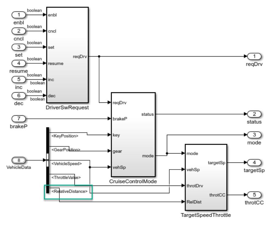
The model adds the RelativeDistance field, highlighted in green, to the VehicleData bus to record the distance from the lead vehicle.
Next, update the control law in the subsystem crs_controller_adaptive/TargetSpeedThrottle/activated/getThrottleValue/PI controller to use RelativeDistance.
open_system("crs_controller_adaptive/TargetSpeedThrottle/activated/getThrottleValue/PI controller");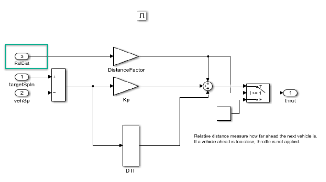
Observe that when you add the RelativeDistance field to the bus highlighted in green, you make all previously generated test cases in crs_controller_basic_sldvdata.mat incompatible with simulation.
The input interface assumed by the earlier test cases no longer matches crs_controller_adaptive.
Update Test Cases for the New Model Interface
Use sldvoptions to update test cases in crs_controller_basic_sldvdata.mat file.
opts = sldvoptions(updatedModel);
opts.ExtendExistingTests = "on";    % Enable loading of existing test cases
opts.ExistingTestFile = "crs_controller_basic_sldvdata.mat";  % Specify file containing existing test cases
You may enable this workflow by following this:
Click Model Settings > Design Verifier > Test Generation in the Simulink Design Verifier configuration parameters.
Select Test Generation in the left pane, then expand Advanced parameters.
Select Extend using existing test data and specify the MAT file in the Test data field.
[status,updatedFiles] = sldvrun(updatedModel,opts);
07-Aug-2026 02:56:45
Checking compatibility for test generation: model 'crs_controller_adaptive'
Compiling model...done
Building model representation...done

07-Aug-2026 02:56:52

'crs_controller_adaptive' is compatible for test generation with Simulink Design Verifier.

07-Aug-2026 02:56:52
Loading initial test data...done
Generating tests...


Generating output files:

07-Aug-2026 02:57:27
Results generation completed.

    Data file:
    /tmp/Bdoc26b_3351752_1692667/tpb42daa41/sldv-ex95711172/sldv_output/crs_controller_adaptive/crs_controller_adaptive_sldvdata.mat
View Updated Test Cases
Review the updated test cases in Simulink Design Verifier report.
sldvreport(updatedFiles.DataFile);
View Relationship Between Original and Updated Test Cases
The image shows how Simulink Design Verifier updates test cases. You can see the updated Test Case 1 in the report.
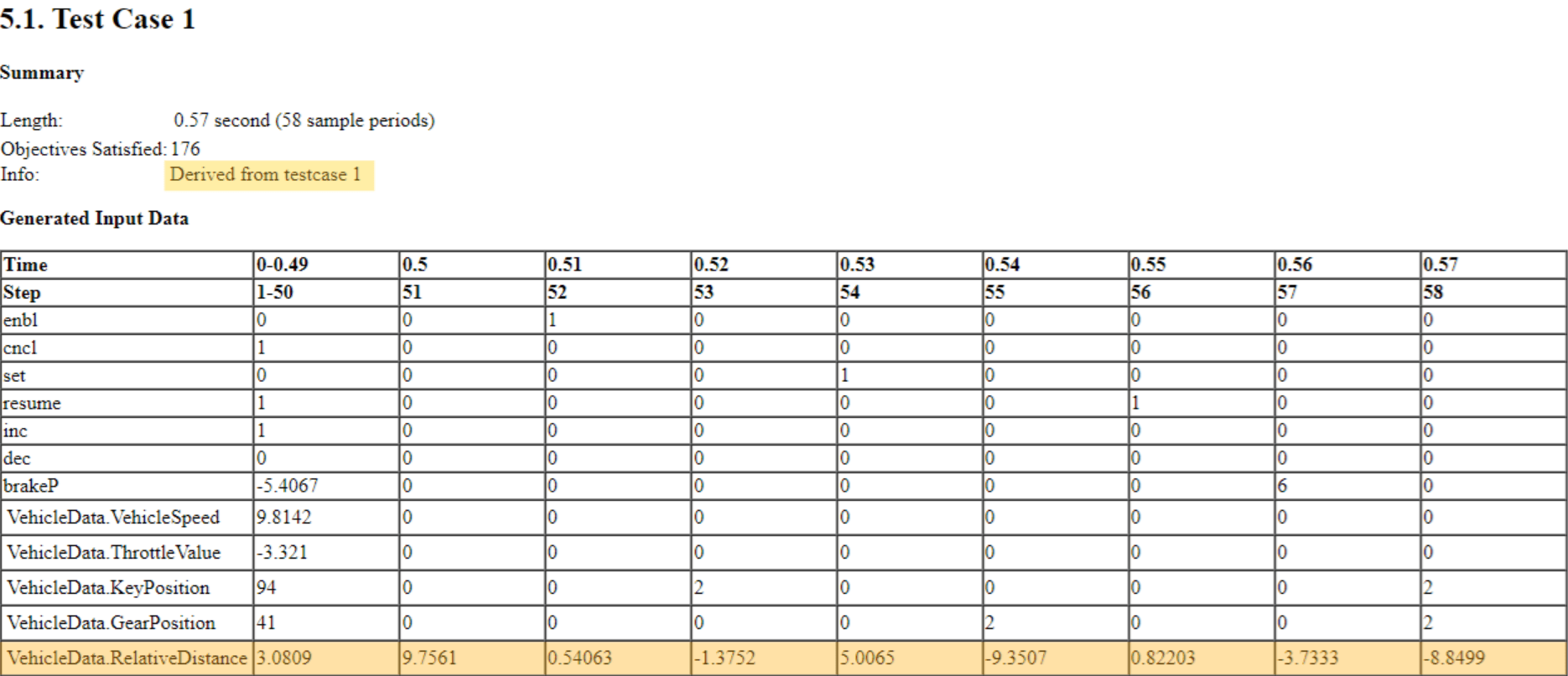
Updated Test Case 1 includes this information:
The
Infofield that specifies metadata about each test case or counterexample. For more information onInfofield,see the table that describes the TestCases and CounterExamples fields in View and Understand Analysis Results from Data Files.The last row that contains generated data for input
VehicleData.RelativeDistance.All the other rows that include
TimeandStep,are copied from the source test case.
In this example, the Info field in the Summary section shows that updated Test Case 1 was derived from the original Test Case 1. When you update test cases, Simulink Design Verifier preserves time, steps, and data for all unchanged inputs, and generates values only for newly added or modified signals. If existing test cases do not satisfy all objectives in the updated model, Simulink Design Verifier creates additional test cases as needed.
Simulink Design Verifier identifies added, deleted, or modified signals by matching their exact names from the generated input data file. If you change a signal’s name, data type, or size in the updated model, the test case data of the signal is not preserved. If signal properties remain unchanged or you only reorder signals, Simulink Design Verifier retains their test data.
close_system(model,0);
close_system(updatedModel,0);

