Main Content

Weld Joint

Joint with zero primitives

Library

Joints

  • Weld Joint block

Description

This block represents a joint with zero degrees of freedom. It contains no joint primitives. Base and follower frames, each connected to a separate rigid body, are coincident for all time. The block dialog box provides sensing options for constraint and total forces and torques.

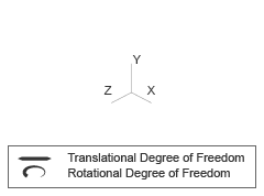
Joint Degrees of Freedom
Faults

Using mode faults, you can change the joint modes during a simulation without modifying the model design. The fault injection overrides the mode setting. For example, if a joint has the Mode parameter set to Locked and the Fault behavior parameter set to Disengaged, the joint becomes disengaged.

To add a mode fault to a joint block, click on the joint block, in the Simscape Block tab, and the Faults section, click Fault > Add Fault. Alternatively, you can click the joint block, hover over the ellipsis to open the action bar, and click the Add a fault on the block icon Button to use to add a fault. You can add multiple faults to a joint block, but the joint block can have only one active fault during a simulation.

As you add faults, in the Property Inspector, under the Fault section, specify the behavior and the trigger type of the fault. To define the fault behavior, click the link next to the Fault Behavior. This joint supports Normal or Disengaged mode. The joint blocks support these trigger types: Always on, Timed, Manual, and Conditional. For more details of these trigger types, see Set Fault Triggers. To trigger a conditional fault, you can use Simulink signals, Simscape language blocks, and MATLAB workspace variables. To set the active fault for a block, use the Fault Table. For more details, see Access the Fault Table and Fault Dashboard.

To enable fault simulation, in the Simscape Block tab and the Faults section, turn on the Fault Simulation button. The fault simulation is on when the button is green and the status is on. The simulation logs the trigger status data. To view the data, use the Simulation Data Inspector. Also, you can see the fault status and a summary of the triggered faults in the Fault Dashboard. To open the Fault Dashboard, in the Simscape Block tab, click Faults > Fault Dashboard.

To create and modify faults, you can also use Simscape™ and Simulink® fault functions. For more details, see the function section of the Simulink Fault Controls and Simscape Faults Interface.

Parameters

Mode Configuration

Specify the mode of the joint. The joint mode can be normal or disengaged throughout the simulation, or you can provide an input signal to change the mode during the simulation.

Mode

Select one of the following options to specify the mode of the joint. The default setting is Normal.

MethodDescription
NormalThe joint behaves normally throughout the simulation.
DisengagedThe joint is disengaged throughout the simulation.
Provided by InputThis option exposes the mode port that you can connect to an input signal to change the joint mode during the simulation. The joint mode is normal when the input signal is 0 and disengaged when the input signal is -1. The joint mode can be changed many times during the simulation.

Composite Force/Torque Sensing

Select the composite forces and torques to sense. Their measurements encompass all joint primitives and are specific to none. They come in two kinds: constraint and total.

Constraint measurements give the resistance against motion on the locked axes of the joint. In prismatic joints, for instance, which forbid translation on the xy plane, that resistance balances all perturbations in the x and y directions. Total measurements give the sum over all forces and torques due to actuation inputs, internal springs and dampers, joint position limits, and the kinematic constraints that limit the degrees of freedom of the joint.

Direction

Vector to sense from the action-reaction pair between the base and follower frames. The pair arises from Newton's third law of motion which, for a joint block, requires that a force or torque on the follower frame accompany an equal and opposite force or torque on the base frame. Indicate whether to sense that exerted by the base frame on the follower frame or that exerted by the follower frame on the base frame.

Resolution Frame

Frame on which to resolve the vector components of a measurement. Frames with different orientations give different vector components for the same measurement. Indicate whether to get those components from the axes of the base frame or from the axes of the follower frame. The choice matters only in joints with rotational degrees of freedom.

Constraint Force

Dynamic variable to measure. Constraint forces counter translation on the locked axes of the joint while allowing it on the free axes of its primitives. Select to output the constraint force vector through port fc.

Constraint Torque

Dynamic variable to measure. Constraint torques counter rotation on the locked axes of the joint while allowing it on the free axes of its primitives. Select to output the constraint torque vector through port tc.

Total Force

Dynamic variable to measure. The total force is a sum across all joint primitives over all sources—actuation inputs, internal springs and dampers, joint position limits, and kinematic constraints. Select to output the total force vector through port ft.

Total Torque

Dynamic variable to measure. The total torque is a sum across all joint primitives over all sources—actuation inputs, internal springs and dampers, joint position limits, and kinematic constraints. Select to output the total torque vector through port tt.

Ports

This block has two frame ports. It also has optional physical signal ports for sensing dynamical variables such as forces, torques, and motion. You expose an optional port by selecting the sensing check box corresponding to that port.

Frame Ports

  • B — Base frame

  • F — Follower frame

Sensing Ports

The following sensing ports provide the composite forces and torques acting on the joint:

  • fc — Constraint force

  • tc — Constraint torque

  • ft — Total force

  • tt — Total torque

Mode Port

Mode configuration provides the following port:

  • mode — Value of the mode of the joint. If the input is equal to 0, the joint behaves normally. If the input is equal to -1, the joint behaves as disengaged.

Extended Capabilities

expand all

C/C++ Code Generation
Generate C and C++ code using Simulink® Coder™.

Version History

Introduced in R2012a

expand all