Getting Started with USB Camera
This example shows how to get started with USB video capture and processing by using SoC Blockset™ Support Package for AMD® FPGA and SoC Devices.
This example tests the data path from a USB based camera connected on a AMD Zynq® UltraScale+(TM) ZCU106 device or AMD Zynq® UltraScale+(TM) ZCU102 device to the host by capturing the camera output into a Simulink® model.
Setup
Before running this model, your hardware must be set up and connected to the host machine running Simulink. If you have not yet done so, run through the guided setup wizard portion of the SoC Blockset Support Package for AMD FPGA and SoC Devices installation. You might have already completed this step when you installed this support package.
On the MATLAB Home tab, in the Environment section of the toolstrip, click Add-Ons > Manage Add-Ons. Locate SoC Blockset Support Package for AMD FPGA and SoC Devices, and click Setup.
Live Video Capture from Target
The main purpose of this example is to check that the target development board has been set up correctly, and that it can communicate with the host platform.
open_system('soc_gettingStarted_USBCamera');
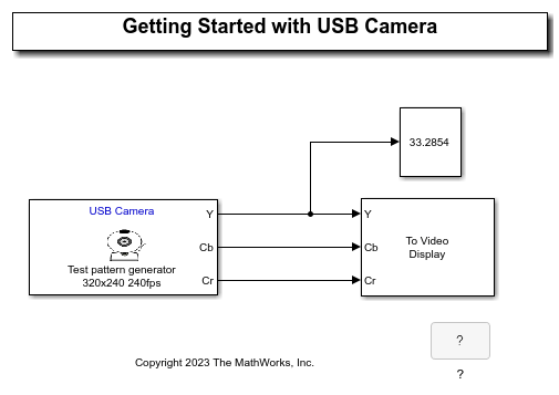
The Video Capture USB block receives captured image data from the target hardware and imports it into Simulink as source data for simulation. The mask parameters allow you to configure the format of the captured data using the target hardware. The block is configured as shown.
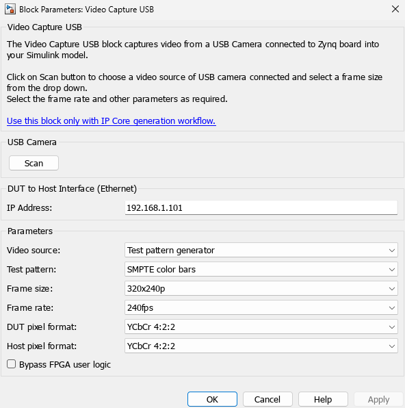
These parameters specify:
A IP address of the target HW on which USB Camera source is connected.
A video source from the Camera sensor connected via USB Port.
A video frame size of
320x240pA video frame rate of
30fpsA DUT pixel format of
YCbCr 4:2:2.A Host pixel format of
YCbCr 4:2:2.Bypass FPGA user logic is unchecked. This is the default option.
The To Video Display block displays the video frames received by the Video Capture USB block. The block is configured to display frames in YCbCr format.
Running the Example
This example captures the camera input from the camera source connected via USB port. When the simulation is running, the Captured Image Display scope opens. You should see the live video frames from the scene your camera is pointed at.
Next Steps
You have used this model to confirm your hardware setup and connection to Simulink. Next, see Frame-Based Video Pipeline Using Zynq UltraScale+ and USB Camera (Vision HDL Toolbox).