Guidelines for Configuring the Software Interface Model
The SoC Blockset™ Support Package for AMD FPGA and SoC Devices lets you configure the software interface model for your specific application. You can set up the software for a packet-based or a continuously running system. The table contains suggested strategies for some common setups and links to more details.
| Operating Mode | Other Processing | Scheduler | Underflow / Data Valid | Overflow | Notes |
|---|---|---|---|---|---|
N/A | Tx interrupt | Stop execution | N/A | ||
N/A | Timer and infinite timeout | Ignore | N/A | Tx block is in enabled subsystem Frame size is equal to packet size | |
N/A | Rx interrupt | N/A | Model stop | ||
No | Rx interrupt | N/A | Per application | ||
Yes | Timer | Drive enabled subsystem | Per application | Frame size is equal to expected packet size |
You can optimize the software interface model by configuring these interacting factors:
Software processing load — Determine the software processing load by allocating the algorithm between the ARM® processor and the FPGA. See Step 3. Create Algorithm and Partition the Design of the Hardware-Software Co-Design Workflow.
Frame rate — Configure the frame rate so that the required software processing can be done in the frame period.
Scheduler — Use the model configuration parameters to run from a transmitter interrupt, a receiver interrupt, or a system timer.
Frame timeout — Determine the frame timeout according to your choice of scheduler.
For details about how to configure the frame rate, the scheduler, and the frame timeout, see System Timing.
Continuous Transmission and Reception
When you model a continuously running system, the transfer of data between the FPGA and the ARM is the most important part of the system. Therefore, configure the scheduler to run from interrupts, so that transmit overflow and receive underflow (data valid de-asserted) do not occur during normal operation. Because a transmit underflow or a receive overflow is a fault condition, you can use a Stop Simulation block to halt operation. These conditions usually occur because of a misconfigured frame rate in the context of the RF baseband sample rate and user logic functionality.
When the model runs from a transmitter or receiver interrupt, other model processing must occur between interrupts. If the model requires that the ARM process other functionality at a higher rate than the data transfer rate, run your model on a timer schedule.
Continuous Transmitter
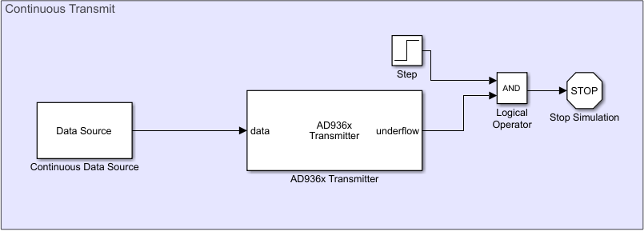
A representative continuous transmitter model includes a continuous data source, a transmitter, and logic to handle underflow conditions.

When you configure the transmitter with a transmitter interrupt, a transmit overflow does not occur because the transmitter triggers only when it has a buffer available.
A transmit underflow indicates a misconfigured frame rate in the context of the RF baseband sample rate and user logic functionality. Use a Stop Simulation block to halt operation when an underflow occurs.
The hardware can detect an underflow while the software is loading the first frames of data. To ignore underflows for the first frame periods, add a Step source block.
When you configure the model to run from the transmitter interrupt, the transmitter timeout parameter of the Transmitter block does nothing.
Continuous Receiver
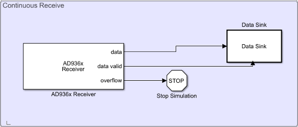
A representative continuous receiver model includes a receiver block, logic for extracting and validating data, and logic for handling overflows.

In this representative model, the AD936x
Receiver block has its data valid port
enabled. This port is enabled whenever the Data timeout
(sec) parameter on the Advanced tab is
set to a value other than Inf.
When the scheduler uses a receiver interrupt, the data valid signal does not de-assert during normal operation. As a best practice, place the receive processing logic (the data sink) in an enabled subsystem driven by the data valid output.
Overflow indicates a misconfigured frame rate in the context of the RF baseband sample rate and user logic functionality. Use a Stop Simulation block to halt operation when overflow occurs.
When you configure the model to run from the receiver interrupt, the receiver timeout of the Receiver block does nothing.
Packet Transmission and Reception
A packet-based system cannot predict when the receiver receives data or when the transmitter sends data.
Packet Transmitter
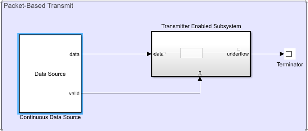
A representative packet-based transmitter model includes a packet data source and an enabled subsystem containing a transmitter block.

For packet-based transmission, configure the model to run on a timer-based schedule. To control whether the data is sent into the transmitter on each system base rate tick, enclose the Transmitter block in an enabled subsystem. Use a separate control signal to enable or disable transmission.
Because the system is packet-based, underflows between packets occur during normal operation. You can ignore (terminate) the underflow output port.
In the Transmitter block, set the Data timeout
(sec) parameter to Inf so that the software waits
until it has data ready to send. While the software waits, the transmit user logic on
the FPGA accepts more samples and a transmitter buffer eventually becomes free.
During normal operation, the software does not time out and overflow does not occur.
Overflow indicates a misconfigured frame rate in the context of the RF baseband sample rate and user logic functionality.
Packet Receiver
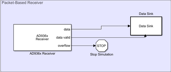
A representative packet-based receiver model includes a packet receiver block, logic for extracting and validating data, and logic for handling overflows.

In this representative model, the AD936x
Receiver block has its data valid port
enabled. This port is enabled whenever the Data timeout
(sec) parameter on the Advanced tab is
set to a value other than Inf.
For packet-based reception, consider whether your model must do other processing, such as AXI register reads and writes that are asynchronous to the arrival of data. If the model does require other processing, use a timer-driven scheduler. If other processing is done only when data arrives, use a receiver-interrupt scheduler.
Enclose the software (the data sink) in a subsystem enabled by the data valid port of the Receiver block. When driven by receiver interrupt, under normal operation, the data valid port remains asserted. When driven by the timer, under normal operation, the data valid signal prevents the software from processing invalid data.
Overflow indicates a misconfigured frame rate in the context of the RF baseband sample rate and user logic functionality. Use a Stop Simulation block to halt operation when overflow occurs.
Combined Transmission and Reception
Many applications require both transmission and reception of data in the same system. To configure these models, consider the priorities of the different aspects of your system and set up the scheduler accordingly.
Suppose that continuous data transmission is crucial to your system. Configure your model as follows:
Drive the model from the transmit interrupt.
Configure the transmit frame period so that you can do additional processing, such as receiving data and controlling the hardware, during the transmit frame period.