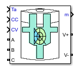
CCCV Battery Charger
Constant-current constant-voltage battery charger
Description
The CCCV Battery Charger block implements a generic dynamic model battery charger. This model supports three-phase wye or delta AC, one-phase AC, or DC voltage input. The model also provides an optional ambient temperature input for charging voltage temperature compensation.
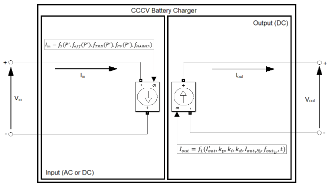
The figure shows the equivalent circuit for the CCCV Battery Charger block.
Equations
The output current of the battery charger is
Variables for the output current and related equations are:
Iout is the output current command, in A.
I'out is the pre-filtered current command, in A.
kp is the PID filter proportional gain.
ki is the PID filter integral gain.
kd is the PID filter differential gain.
Ioutr% is the current output ripple, in %.
foutir is the current output ripple frequency, in Hz.
t is the time, in s.
ξ is the dampening factor, which is limited to values between
0and0.9.⍵n is the is radian frequency, in rad/s.
d% is the overshoot, in %.
ts is the settling time, in s.
ICC is the pre-filtered current regulated current command, in A.
Ibulk is the constant current command, in A.
ICV is the pre-filtered voltage regulated current command, in A.
V'out is the voltage command, in V.
V'tc is the voltage command, in V.
Vout is the temperature compensated voltage effect, in V.
is the mean measured output voltage, in V.
Ta is the ambient temperature, in °C.
Tnom is the nominal ambient temperature, in °C.
Vtc is the voltage compensation ratio, in V/°C.
Vabs is the absorption voltage, in V.
Vfloat is the float voltage, in V.
P is the output power, in W.
is the mean measured output current, in A.
The control gains are:
The dampening factor is
When the output control is current regulated the radian frequency is
When the output control is voltage regulated the radian frequency is
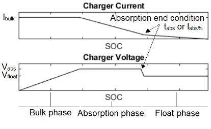
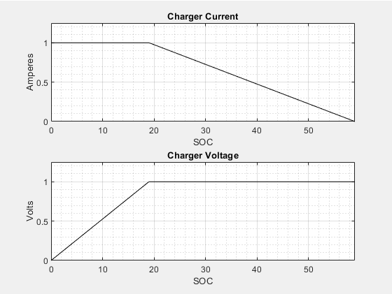
The pre-filtered current command, I'out, is provided either from the pre-filtered current regulated current command, ICC, or from the pre-filtered voltage regulated current command, ICV. The graphs show the different charging cycle phases.
If the Output control mode is set to
Constant Current only (CC) or
Constant Current - Constant Voltage (CCCV) and
Vout is lower than Float voltage or Absorption
voltage, while the Absorption end
condition isn’t met
If the Output control mode is set to
Constant Current only (CC) or
Constant Current - Constant Voltage (CCCV) and
Vout is equal to the Float voltage or Absorption
voltage, while the Absorption end
condition isn’t met
When the Enable absorption phase option is selected and the battery charger switches from constant current to constant voltage control, if the Absorption end condition is not met, the ambient temperature voltage compensation, V'tc is defined as
Otherwise, the ambient temperature voltage compensation, V'tc is defined as
When the Enable absorption phase option is selected and the battery charger switches from constant current to constant voltage control, if the Absorption end condition is not met, the ambient temperature voltage compensation, V'out is defined as
Otherwise, the ambient temperature voltage compensation, V'out is defined as
The output power is defined as
The input current of the battery charger is
Variables for the input current and related equations are:
Iin is the input current command, in A.
P' is the normalized output power.
P is the output power, in W.
Pnom is the nominal output power, in W.
I'n is the normalized harmonic amplitude.
fin is the input voltage frequency, in Hz.
fn is the harmonic frequency, in Hz.
t is the time, in s.
VinA is the input voltage delayed by the fifth of its period, in V.
Vin is the input voltage of phase A delayed by the fifth of its period, in V.
Iinr% is the input current ripple, in %.
finir is the input current ripple frequency, in Hz.
θVin is the input voltage angle, in rad.
θVinA is the input voltage angle of phase A, in rad.
Where, feff, is a polynomial function following the parameters Charger efficiency and Efficiency usage factor. This polynomial order is half of the number of data pairs entered. For input values of, P', between 0 and 1, the polynomial must return values between 0 and 1. Otherwise, the polynomial order is reduced until this condition is met. If the order reaches 0, the output will remain constant for the mean value of the dataset.
Where, fTHD, is a polynomial function following the parameters Total harmonic distortion and THD usage factor. This polynomial order is half of the number of data pairs entered. For input values of, P', between 0 and 1, the polynomial must return values between 0 and 1. Otherwise, the polynomial order is reduced until this condition is met. If the order reaches 0, the output will remain constant for the mean value of the dataset.
Where, fPF, is a polynomial function following the parameters Power factor and PF usage factor. This polynomial order is half of the number of data pairs entered. For input values of, P', between 0 and 1, the polynomial must return values between 0 and 1. Otherwise, the polynomial order is reduced until this condition is met. If the order reaches 0, the output will remain constant for the mean value of the dataset.
Where, fHARMS, is the sum of sine waves specified with the parameters Harmonics amplitude and Harmonics frequency following the expression
When the Type parameter is set to
DC,
When the Type parameter is set to 1-phase AC
,
When the Type parameter is set to 3-phase AC
(wye) :
When the Type parameter is set to 3-phase AC
(delta) :
Where:
Assumptions and Limitations
Model Assumptions
The output load consists of an adequately sized battery.
Three-phase alternative current inputs are balanced, synchronized, and without jitter.
The ambient temperature does not affect the charger’s parameters.
Limitations
The output power is independent from the input power.
Ports
Input
Output
Conserving
Parameters
General
Preset — Parameterization method
Custom
							specifications
(default) | Primax P4500F-3-125-10 | Transtronic 020-0085-00
The parameter contains a list of two predetermined battery chargers. The parameters in the CCCV Battery Charger block are not enabled when a preset is selected.
Nominal power (W) — Nominal power
1500 (default)
The nominal power, Pnom, of the battery charger in W. The nominal power is used for normalized parameters Charger efficiency, Total harmonic distortion and Power factor. This parameter must be greater than or equal to the product of Bulk current and Float voltage or Absorption voltage if Enable absorption phase is selected.
Input
Type — Input voltage type
3-phases AC (wye) (default) | 3-phases AC (delta) | 1-phase AC | DC
Input voltage type:
3-phases AC (wye)— The A, B, and C ports become visible to supply the balanced three-phase alternating current power.3-phases AC (delta)— The A, B, and C ports become visible to supply the balanced three-phase alternating current power.1-phases AC— The A and B ports become visible to supply the balanced single-phase alternating current power.DC— The + and - ports become visible to supply the direct current power.
External neutral connection — Neutral connection option
cleared (default) | selected
Option to enable access to a neutral connection externally through the N port. Otherwise, the neutral is internally connected.
Dependencies
This option is enabled when the Type
is set to 3-phases AC
(wye).
Effective voltage (V) — Effective voltage
208 (default)
Effective voltage, Veff, of
the battery charger power input in V. When Type is
either 3-phases AC (wye) or
 3-phases AC
									(delta)
, the effective
voltage must the rms line voltage.
Frequency (Hz) — Frequency
60 (default)
Frequency, fin, of the battery charger power input in Hz.
Dependencies
This parameter is accessible when Type is set to 3-phases
AC (wye), 3-phases AC
(delta), or 1-phase
AC.
Current ripple (%) — Current ripple
10 (default)
Current ripple, I(inr%), of the battery charger input current.
Dependencies
This parameter is accessible when Type is set to DC
(wye).
Ripple frequency (Hz) — Ripple frequency
1000 (default)
Ripple frequency of the battery charger input current.
Dependencies
This parameter is accessible when Type is set to DC
(wye).
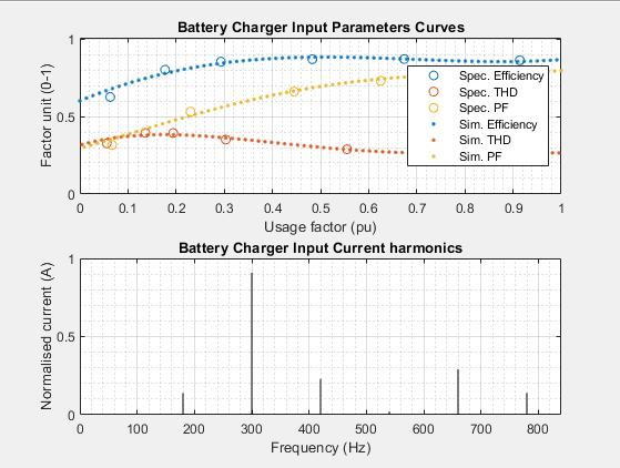
Plot Curves — Click to plot input parameter and input current harmonics curves for the battery charger.
Simulate efficiency — Efficiency simulation option
cleared (default) | selected
Option to simulate efficiency.
Dependencies
When this parameter is selected, the parameters Charger
efficiency and Efficiency usage
factor become visible. Otherwise, the battery charger
efficiency factor is set to a constant value of
1.
Charger efficiency [0-1] — Battery charger efficiency factor
[0.627 0.803 0.855 0.871 0.872
0.864] (default)
Efficiency factor, ηy, of the battery charger. This parameter is used with the Efficiency usage factor to approximate a polynomial function corresponding to the full operation range efficiency normalized on the Nominal Power.
Efficiency usage factor (pu) — Battery charger efficiency usage factor
[0.063 0.177 0.293 0.483 0.674
0.914] (default)
Efficiency usage factor of the battery charger. This parameter is used with the Charger efficiency to approximate a polynomial function corresponding to the full operation range efficiency normalized on the Nominal Power.
Simulate THD — THD simulation option
cleared (default) | selected
Total harmonic distortion (THD) simulation option.
Dependencies
When this parameter is selected, the parameters Total
harmonic distortion, THD usage
factor, Harmonics amplitude, and
Harmonics frequency become visible.
Otherwise, the battery charger THD factor is
set to a constant value of 0.
Total harmonic distortion [0-1] — THD
[0.327 0.394 0.394 0.351 0.289
0.265] (default)
The total harmonic distortion factor, THDy, of the battery charger. This parameter is used with the THD usage factor (pu) to approximate a polynomial function corresponding to the full operation range THD normalized on the Nominal Power.
THD usage factor (pu) — THD usage factor
[0.056 0.136 0.194 0.303 0.555
0.916] (default)
The total harmonic distortion usage factor, THDy, of the battery charger. This parameter is used with the Total harmonic distortion [0-1] to approximate a polynomial function corresponding to the full operation range THD normalized on the Nominal Power.
Harmonics amplitude (A) — Harmonic amplitude
[0.199 1.297 0.328 0.029 0.416
0.200] (default)
Harmonics amplitude, In, of
the battery charger input current in A. This parameter is used with the
Harmonics frequency to generate the
battery charger’s input current harmonics signature. The harmonics
amplitude parameter’s values are normalized to 1
using this:
Dependencies
This parameter is accessible when the Type is
set to 3-phases AC (wye),
3-phases AC (delta), or
1-phase
									AC
.
Harmonics frequency (n) — Harmonic frequency
[3 5 7 9 11 13] (default)
The harmonics frequency, fn, of the battery charger’s input current in n multiples of Frequency. This parameter is used with the Harmonics amplitude to generate the battery charger’s input current harmonics signature.
Dependencies
This parameter is accessible when the Type is
either 3-phases AC (wye),
3-phases AC
									(delta)
, or
1-phase
									AC
.
Simulate power factor — Power factor simulation option
cleared (default) | selected
Option to simulate power factor. Otherwise, the battery charger’s PF
is set to a constant equal to 1.
Dependencies
This parameter is accessible when the Type
is set to 3-phases AC
(wye), 3-phases AC
(delta), or 1-phase
AC. When this parameter is selected, the
parameters Power factor and
PF usage factor become
visible.
Power factor [0-1] — Power factor
[0.316 0.532 0.662 0.731 0.780
								0.792]
(default)
Total harmonic distortion factor, or power factor, PFy, of the battery charger. This parameter is used with the PF usage factor to approximate a polynomial function corresponding to the full operation range’s PF normalized on the Nominal Power.
Dependencies
This parameter is accessible when the Type
is set to 3-phases AC
(wye), 3-phases AC
(delta), or 1-phase
AC.
PF usage factor (pu) — Power factor usage factor
[0.067 0.230 0.445 0.625 0.794
								0.919]
(default)
The PF usage factor, PFy, of the battery charger. This parameter is used with the Power factor to approximate a polynomial function corresponding to the full operation range PF normalized on the Nominal Power
Charging Mode
Output control mode — Output control method
Constant Current - Constant Voltage
								(CCCV)
(default) | Constant Current only (CC) | Constant Voltage only (CV)
Methods for output control are:
Constant Current - Constant Voltage
										(CCCV)
— This charging mode regulates the output current and voltage.Constant Current only (CC)— This charging mode regulates the output current.Constant Voltage only (CV)— This charging mode regulates the output voltage.
Dependencies
Different options expose different parameters.
Dynamic input thresholds — Dynamic input thresholds option
selected (default) | cleared
Option to enable dynamic access to the output current and voltage thresholds. Otherwise, these thresholds are set withBulk current and Float voltage or Absorption voltage.
Dependencies
The CC or CV input ports become visible to supply the current and voltage thresholds depending on the Output control mode selected.
Bulk current (A) — Bulk current
10 (default)
The bulk current, Ibulk, of the battery charger maximum output current in A. While the output voltage is lower than Float voltage or Absorption voltage, the battery charger limits the output current to maintain a constant current.
Dependencies
This parameter is accessible when the Output control
mode is either Constant
Current - Constant Voltage (CCCV) or Constant Current only (CC).
Float voltage (V) — Float voltage
138 (default)
Float voltage, Vfloat, of the battery charger steady-state output voltage in V. When the output voltage reaches this value, the battery charger reduces the output current to maintain a constant voltage.
Dependencies
This parameter is accessible when the Output control
modeis either Constant
Current - Constant Voltage (CCCV) or Constant Voltage only (CV).
Enable absorption phase — Absorption phase option
cleared (default) | selected
Option to enable the battery charging absorption phase. The charging phase allows the battery charger to maintain a higher Absorption voltage than Float voltage for a specified Absorption end condition when switching from constant current to constant voltage charging.
Dependencies
This parameter is accessible when the Output
control mode is Constant
Current - Constant Voltage (CCCV) and the
Dynamic input thresholds is
cleared.
Absorption voltage (V) — Absorption voltage
142 (default)
Absorption voltage, Vabs, of the battery charger transition voltage when switching from constant current to constant voltage charging. The battery charger’s absorption voltage will be maintained while the Absorption end condition isn’t met. This parameter must be greater than the float voltage.
Dependencies
This parameter is accessible when the Enable absorption phase is selected.
Absorption end condition — Absorption end condition
Time based (default) | Current based
Choose between two absorption end conditions:
Time based— This end condition requires a specified Absorption time while maintaining the Absorption voltage before lowering the battery charger’s output voltage to Float voltage.Current based— This end condition requires a specified Absorption current while maintaining the Absorption voltage before lowering the battery charger’s output voltage to Float voltage.
Dependencies
This parameter is accessible when Enable absorption phase is selected.
Absorption time (s) — Absorption time
3600 (default)
Absorption time, tabs, of the time-based end condition of the absorption phase in s. When the Absorption voltage has been maintained for the specified time, the output voltage is lowered to the Float voltage.
Dependencies
This parameter is accessible when the Absorption end
condition is Time
based.
Absorption current (%) — Absorption current
40 (default)
Absorption current, Iabs%,
of the absorption phase’s current-based end condition in %. When the
output current reaches the specified percentage of the Bulk
current, the output voltage lowers from the
Absorption voltage to the Float
voltage. This parameter is accessible when the
Absorption end condition is Current based.
Dependencies
This parameter is accessible when the Absorption end
condition is Current
based.
Plot Curves — Click to plot input parameter and input current harmonics curves for the battery charger.
Output
Current ripple (%) — Current ripple
0.5 (default)
The output ripple, Ioutr%, of the battery charger current specified as a %.
Ripple frequency (Hz) — Ripple frequency
1000 (default)
foutir
Ripple frequency, foutir, of the battery charger output current in Hz.
Overshoot (%) — System overshoot
1 (default)
The overshoot, d%, of the battery charger’s output control dynamic in %. This parameter is applied to the Bulk current, Float voltage and Absorption voltage depending on charging phase.
Settling time (s) — System settling time
5 (default)
Settling time, ts, at which the battery charger’s output control dynamic reaches 2% of its steady-state value in s. This parameter is applied to the Bulk current, Float voltage and Absorption voltage depending on charging phase.
Dependencies
Simulate voltage compensation — Voltage compensation option
cleared (default) | selected
Option to enable output voltage temperature compensation. When enabled, the Float voltage and Absorption voltage will vary depending on the ambient temperature, Voltage compensation and Nominal temperature.
Voltage compensation (V/deg. C) — Voltage compensation
-0.18 (default)
Voltage compensation, Vtc, of the battery charger output in V/°C.
Dependencies
This parameter is accessible when the Simulate voltage compensation is selected.
Nominal temperature (deg. C) — Nominal temperature
20 (default)
Nominal temperature, Tnom, of the required battery float voltage in °C.
Dependencies
This parameter is accessible when the Simulate voltage compensation is selected.
References
[1] Cope, R.C., and Y. Podrazhansky. The Art of Battery Charging. Proc. 14th Annual Battery Conference on Applications and Advances, pp. 233-235. Long Beach, CA: 1999.
[2] Dubey, A., Santoso, S., and M.P. Cloud. Average-Value Model of Electric Vehicle Chargers. IEEE Transactions on Smart Grid Vol. 4 No. 3. Pp. 1549-1557. Argonne, IL: IEEE Power & Energy Society, 2013.
[3] Elias, M., Nor, K., and A. Arof. Design of Smart Charger for Series Lithium-Ion Batteries. Proceedings from IEEE International Conference on Power Electronics and Drive Systems, pp. 1485-1490. Kuala Lumpur: PEDS, 2005.
[4] Hussein A.A.-H., and I. Batarseh. A Review of Charging Algorithms for Nickel and Lithium Battery Chargers. IEEE Transactions on Vehicular Technology. Sendai, Japan: IEEE Vehicular Technology Society, 2011.
Version History
Introduced in R2019a
You can also select a web site from the following list:
Americas
- América Latina (Español)
- Canada (English)
- United States (English)
Europe
- Belgium (English)
- Denmark (English)
- Deutschland (Deutsch)
- España (Español)
- Finland (English)
- France (Français)
- Ireland (English)
- Italia (Italiano)
- Luxembourg (English)
- Netherlands (English)
- Norway (English)
- Österreich (Deutsch)
- Portugal (English)
- Sweden (English)
- Switzerland
- United Kingdom (English)