Three-Phase Tap-Changing Transformer (Two-Windings)
Libraries:
Simscape /
Electrical /
Specialized Power Systems /
Power Grid Elements
Description
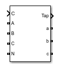
The Three-Phase Tap-Changing Transformer (Two Windings) block models a three-phase, tap-changing transformer with two windings. The tap changer is on winding 1. Winding 1 is connected in wye. Winding 2 can be connected in wye or delta.
The transformer voltage ratio is determined by the position of the tap and by the
method used to control it. When Mode is set to
Tap control
, the position of the tap is controlled by the
input signal. When Mode is set to Voltage
regulation
, the position of the tap is controlled by an internal
voltage regulator that compares the input signal to the reference voltage.
When you use a Three-Phase Tap-Changing Transformer block, set the powergui block Simulation type to Discrete
and select
Automatically handle Discrete solver. The robust
discrete solver is used to discretize the electrical model. Simulink® returns an error if the robust discrete solver is not used.
Examples
OLTC Regulating Transformer
A tap-changing transformer that regulates positive sequence voltage at a 25 kV bus
Ports
Conserving
A – Winding 1 phase A terminal — Electrical conserving port
specialized electrical
Electrical conserving port associated with the phase A terminal of winding 1.
B – Winding 1 phase B terminal — Electrical conserving port
specialized electrical
Electrical conserving port associated with the phase B terminal of winding 1.
C – Winding 1 phase C terminal — Electrical conserving port
specialized electrical
Electrical conserving port associated with the phase C terminal of winding 1.
N – Winding 1 neutral terminal — Electrical conserving port
specialized electrical
Electrical conserving port associated with the neutral terminal of winding 1.
a – Winding 2 phase A terminal — Electrical conserving port
specialized electrical
Electrical conserving port associated with the phase A terminal of winding 2.
b – Winding 2 phase B terminal — Electrical conserving port
specialized electrical
Electrical conserving port associated with the phase B terminal of winding 2.
c – Winding 2 phase C terminal — Electrical conserving port
specialized electrical
Electrical conserving port associated with the phase C terminal of winding 2.
Simulink
ctrl – Control input — Signal used to control tap position
scalar
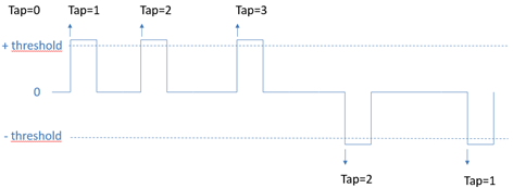
Signal used to control the tap position of the transformer. The tap position of the transformer increases when the ctrl input signal becomes greater than the specified Threshold parameter value. The tap position decreases when the ctrl input signal becomes less than the negative of the Threshold parameter value.
The new tap position becomes effective after the time specified by the Tap selection time parameter.
Dependencies
To enable this port, set Mode to
Tap Control
.
Vm (pu) – Measured voltage signal — Signal used to control tap position
scalar
Signal used to control the tap position of the transformer with an internal voltage regulator. Use the magnitude of voltage, in pu, measured at the secondary winding or at a remote bus.
The tap position of the transformer increases when the difference between the Vm (pu) input signal and the Reference voltage Vref parameter value becomes greater than the value of the Dead band parameter divided by 2, for a time duration greater than the Delay parameter value.
The tap position decreases when the difference between the Vm (pu) input signal and the Reference voltage Vref (pu) parameter value becomes lower than the value of the negative of the Dead band parameter divided by 2, for a time duration greater than the Delay parameter value.
Dependencies
To enable this port, set Mode to
Voltage regulation
.
Tap – Tap position value — Output signal
integer
Output signal that gives the current tap position.
Parameters
Transformer
[Pnom(VA), Fnom(Hz)] – Transformer nominal parameters — Nominal power rating
[ 47e6 , 60] (default) | two-element vector
Nominal power rating, in volt-amperes (VA), and nominal frequency, in hertz (Hz), of the transformer.
Winding 1 connection (ABC) — Winding connection
Yn
(default)
Winding connection for winding 1.
Winding 1 [V1 Ph-Ph(Vrms), R1(pu), L1(pu)] – Winding 1 parameters — Phase-to-phase nominal voltage
[120e3, 0.003, 0.09] (default) | three-element vector
Phase-to-phase nominal voltage, in volts RMS, and resistance and leakage inductance, in pu, for winding 1.
Winding 2 connection (abc) – Winding 2 connection — Winding connection
Delta (D1)
(default) | Y
| Yg
| Delta (D11)
Winding connection for winding 2.
Winding 2 parameters [ V2 Ph-Ph(Vrms), R2(pu), L2(pu)] – Winding 2 parameters — Phase-to-phase nominal voltage
[ 25e3 , 0.003 , 0.09 ] (default) | three-element vector
Phase-to-phase nominal voltage, in volts RMS, and resistance and leakage inductance, in pu, for winding 2.
Core type – Transformer core type — Core type
Three single-phase
transformers
(default) | Three-limb core (core-type)
Select Three single-phase transformers
to
implement a three-phase transformer using three single-phase transformer
models. This core type is used in very large power transformers found in
utility grids.
Select Three-limb core (core type)
to
implement a three-limb core three-phase transformer. In most
applications, three-phase transformers use a three-limb core (core-type
transformer). Selecting this core type will produce accurate results
during an asymmetrical fault for both linear and nonlinear models
(including saturation). During asymmetrical voltage conditions, the
zero-sequence flux of a core-type transformer returns outside the core,
through an air gap, structural steel, and tank. Consequently, the
natural zero-sequence inductance L0 (without delta winding) of a
core-type transformer is usually very low (typically 0.3 pu < L0 <
2 pu) compared with a three-phase transformer that uses three
single-phase units (L0 > 100 pu). This low L0 value affects voltages,
currents, and flux unbalances during linear and saturated
operation.
Inductance L0 of zero-sequence flux path return (pu) – Three-limb core inductance — Inductance L0
0.5 (default) | scalar number
Inductance L0, in pu, of the three-limb core transformer.
Dependencies
To enable this parameter, set Core
Type to Three-limb core (core
type)
.
Rm (pu) – Magnetisation resistance — Magnetization resistance
500 (default) | scalar number
Magnetization resistance Rm, in pu.
Lm (pu) – Magnetization inductance — Magnetization inductance
500 (default) | scalar number
Magnetization inductance Lm, in pu, for a nonsaturable core.
Dependencies
To enable this parameter, clear Simulate saturation.
Simulate saturation – Activate transformer saturation — Implement saturable three-phase transformer
off (default) | on
Select this parameter to implement a saturable three-phase transformer.
[i1 , phi1 ; i2 , phi2 ; ... ] (pu) – Saturation characteristic — Saturation characteristic
[ 0,0 ; 0.0024,1.2 ; 1.0,1.52 ] (default) | matrix
Saturation characteristic for the saturable core. Specify a series of current and flux pairs, in pu, starting with the pair (0, 0).
Dependencies
To enable this parameter, select Simulate saturation.
Specify initial fluxes – Activate initial flux specification — Specify initial fluxes
off (default) | on
If selected, the initial fluxes are defined by the [phi0A, phi0B, phi0C] (pu) parameter.
When the Specify initial fluxes parameter is cleared, the Simscape™ Electrical™ Specialized Power Systems software automatically computes the initial fluxes to start the simulation in steady state. The computed values are saved in the Initial Fluxes parameter and overwrite any previous values.
Dependencies
To enable this parameter, select Simulate saturation.
[phi0A , phi0B , phi0C] (pu) – Initial fluxes — Initial fluxes
[ -1.0 0.5 0.5] (default) | vector of 3 values
Initial fluxes for each phase of the transformer.
When the Specify initial fluxes parameter is not selected upon simulation, the Simscape Electrical Specialized Power Systems software automatically computes the initial fluxes to start the simulation in steady state. The computed values are saved in the Initial Fluxes parameter and overwrite any previous values.
Dependencies
To enable this parameter, select Simulate saturation and Specify initial fluxes.
Measurements – Measurements — Measurements
None
(default) | Winding voltages
| Winding currents
| Fluxes and excitation currents ( Imag + IRm
)
| Fluxes and magnetization currents ( Imag
)
| All measurements (V I Fluxes)
Select Winding voltages
to measure the
voltage across the winding terminals.
Select Winding currents
to measure the
current flowing through the windings.
Select Fluxes and excitation currents ( Imag + IRm
)
to measure the flux linkage, in volt seconds (V.s),
and the total excitation current including iron losses modeled by
Rm.
Select Fluxes and magnetization currents ( Imag
)
to measure the flux linkage, in volt seconds (V.s),
and the magnetization current, in amperes (A), not including iron losses
modeled by Rm.
Select All measurements (V I Fluxes)
to
measure the winding voltages, currents, magnetization currents, and the
flux linkages.
Place a Multimeter block in your model to display the selected measurements during simulation. In the Available Measurements parameter of the Multimeter block, the measurements are identified by a label followed by the block name.
Tap-Changer
Minimum tap position – Minimum tap position of transformer — Minimum tap position
-20 (default) | integer
Minimum tap position of the transformer. This value is typically between -20 and +20. At the minimum tap position, the transformer voltage ratio is:
U2/U1 = 1 /( 1+ Minimum tap position * Voltage step per tap (pu)).
For example, for a minimum tap position of -20 and a voltage step of 0.015, the voltage ratio is:
U2/U1 = 1/(1+ -20*0.015) = 1.428 pu.
Maximum tap position – Maximum tap position of transformer — Maximum tap position
20 (default) | integer
Maximum tap position of the transformer. This value is typically between -20 and +20. At the maximum tap position, the transformer voltage ratio is:
U2/U1 = 1 /(1+ Maximum tap position * Voltage step per tap (pu)).
For example, for a maximum tap position of +20 and a voltage step of 0.015, the voltage ratio is:
U2/U1 = 1/(1+ 20*0.015) = 0.769 pu.
Initial tap position – Initial tap position of transformer — Initial tap position
0 (default) | integer
Initial position of the tap when the simulation starts. The initial position must be a value between the minimum tap position and the maximum tap position. When the tap position is 0, the transformer voltage ratio is equal to 1 pu (nominal value).
Voltage step per tap (pu) – Voltage step between two taps — Voltage step
0.015 (default) | positive scalar
Voltage step between two taps of the transformer, in pu. This value is typically in the order of 0.01 to 0.05 pu.
The transformer voltage ratio is given by:
U2/U1 = 1 /(1+ Tap position * Voltage step per tap (pu)).
For example, a voltage step per tap value of 0.015, and a tap position of -20, would produce a voltage ratio of:
U2/U1 = 1/(1+ -20*0.015) = 1.428 pu.
The value of the Voltage step per tap (pu) parameter must be chosen in accordance with the value specified for the Minimum tap position parameter. Follow this constraint according to the above equation:
Minimum tap position * Voltage step per tap > -1
For example, for a Voltage step per tap (pu) parameter of 0.05 pu, the minimum value you can specify for the Minimum tap position parameter is: -19. A value of –20 gives an infinite voltage ratio and a value lower than -20 yields to a negative voltage ratio, which is not relevant.
Tap selection time (s) – Time delay — Time for tap to move
0.5 (default)
Time for the tap to move from one position to the next. This value is typically between 3 and 10 seconds.
Mode – Tap changer control mode — Control tap position
Tap control
(default) | Voltage regulation
Select Tap control
to control the tap
position of the transformer with the ctrl input signal. Select Voltage
regulation
to control the tap position of the
transformer using an internal voltage regulator monitoring the Vm (pu) input signal.
Threshold – Control value threshold — Control value at which tap changes position
0.5 (default)
Control value at which the tap changes position. To increase the tap position, apply a control signal ctrl greater than this value. To lower the tap position, apply a control signal ctrl smaller than the negative of this value.
Dependencies
To enable this parameter, set Mode to Tap
control
.
Reference voltage Vref (pu) – Voltage regulator reference voltage — Reference voltage
1.0 (default) | positive scalar
Reference voltage of the voltage regulator, in pu.
Dependencies
To enable this parameter, set Mode to Voltage
regulation
.
Dead band (pu) – Voltage regulator dead band — Dead band of voltage regulator
0.03 (default)
Dead band of the voltage regulator, in pu.
Reference voltage of the voltage regulator, in pu.
Dependencies
To enable this parameter, set Mode to Voltage
regulation
.
Delay (sec) – Voltage regulator delay — Delay of voltage regulator
0.4 (default)
Delay of the voltage regulator, in sec.
Dependencies
To enable this parameter, set Mode to Voltage
regulation
.
Extended Capabilities
C/C++ Code Generation
Generate C and C++ code using Simulink® Coder™.
Version History
Introduced in R2021b
MATLAB Command
You clicked a link that corresponds to this MATLAB command:
Run the command by entering it in the MATLAB Command Window. Web browsers do not support MATLAB commands.
Select a Web Site
Choose a web site to get translated content where available and see local events and offers. Based on your location, we recommend that you select: .
You can also select a web site from the following list
How to Get Best Site Performance
Select the China site (in Chinese or English) for best site performance. Other MathWorks country sites are not optimized for visits from your location.
Americas
- América Latina (Español)
- Canada (English)
- United States (English)
Europe
- Belgium (English)
- Denmark (English)
- Deutschland (Deutsch)
- España (Español)
- Finland (English)
- France (Français)
- Ireland (English)
- Italia (Italiano)
- Luxembourg (English)
- Netherlands (English)
- Norway (English)
- Österreich (Deutsch)
- Portugal (English)
- Sweden (English)
- Switzerland
- United Kingdom (English)
Asia Pacific
- Australia (English)
- India (English)
- New Zealand (English)
- 中国
- 日本Japanese (日本語)
- 한국Korean (한국어)