Frequency-Dependent Overhead Line (Three-Phase)
Three-phase overhead line which includes effects that vary as a function of frequency
Libraries:
Simscape /
Electrical /
Passive /
Lines
Description
The Frequency-Dependent Overhead Line (Three-Phase) block represents a high-fidelity frequency-dependent overhead line that offers accurate transient response simulation from 0.01 Hz to 100 kHz.
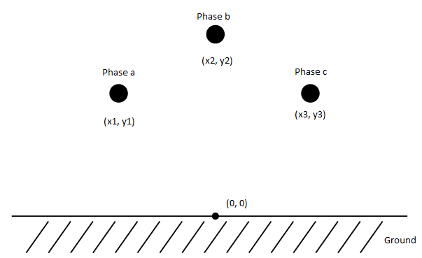
The block computes frequency-dependent impedance and admittance matrices. The calculations also depend on the loss, inductance, and capacitance of the return path.
For more information on using a frequency-dependent overhead line (three-phase), see Engineering Applications.

Equations

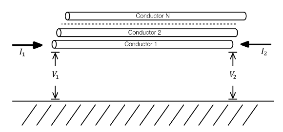
The electromagnetic behavior of a multiconductor transmission line is described by the telegrapher's equation.
Where:
V is the vector of line phase voltages.
I is the vector of phase currents.
Z is the series impedance matrix in per unit length.
Y is the shunt admittance matrix in per unit length.
These are general solutions for the vector of currents and voltages.
| (1) |
| (2) |
Where is the propagation matrix and is the characteristic admittance.
Consider now a transmission line segment of length x = l. At the beginning of one of its ends, when x = 0, the equations 1 and 2 are evaluated as follows.
| (3) |
| (4) |
The integration constant vectors C1 and C2 can be expressed in terms of I0 and V0.
| (5) |
| (6) |
Similarly, at x = l, equations 1 and 2 are evaluated as follows.
| (7) |
| (8) |
To obtain the two fundamental equations for the transmission line model, first you use equations 7 and 8 to perform this calculation.
| (9) |
Then you substitute equation 5 into equation 9.
| (10) |
Where is the propagation factor matrix. Equation 10 establishes the relation between voltages and currents at the terminals of a multi-conductor line section.
You can obtain a companion expression providing the model for the terminal 1 at x = 0.
| (11) |
Define:
— Shunt current vector produced at terminal 1 by injected voltages V1
— Shunt current vector produced at terminal 2 by injected voltages V2
— Reflected currents of terminal 1
— Reflected currents of terminal 2
And finally rewrite equations 10 and 11 as follows:
These equations constitute a traveling wave line model for the segment of length L.

Particularly for transmission lines with ground return, the parameters are highly dependent on frequency. Model solutions are then carried out directly in the phase domain. The block computes automatically the impedance and the characteristic admittance matrices on the full frequency range, performing an approximation through rational fitting.
Rational fitting for this model is performed by using the vector fitting (VF) procedure. For more information on the phase domain line model and the state-space analysis, see Wide-Band Line Model Implementation in Matlab for EMT Analysis [1].
Variables
To set the priority and initial target values for the block variables before simulation, use the Initial Targets section in the block dialog box or Property Inspector. For more information, see Set Priority and Initial Target for Block Variables.
Nominal values provide a way to specify the expected magnitude of a variable in a model. Using system scaling based on nominal values increases the simulation robustness. You can specify nominal values using different sources, including the Nominal Values section in the block dialog box or Property Inspector. For more information, see System Scaling by Nominal Values.
Ports
Conserving
Parameters
More About
References
[1] Ramos-Leanos, O, Iracheta R.. Wide-Band Line Model Implementation in Matlab for EMT Analysis. Arlington, TX: IEEE North American Power Symposium (NAPS), 2010.
[2] Ramos-Leanos, O. Wideband Line/Cable Models for Real-Time and Off-Line Simulations of Electromagnetic Transients. Diss. École Polytechnique de Montréal, 2013.
[3] Ramos-Leanos, O., J. L. Naredo, J. Mahseredjian, I. Kocar, C. Dufour, and J. A. Gutierrez-Robles. A wideband line/cable model for real-time simulations of power system transients. IEEE Transactions on Power Delivery, 27.4 (2012): 2211-2218.
[4] Iracheta, R., and O. Ramos-Leanos. Improving computational efficiency of FD line model for real-time simulation of EMTS. Arlington, TX: IEEE North American Power Symposium (NAPS), 2010.
[5] Dommel, H. W. Electromagnetic transients program (EMTP) theory book. Portland OR: Bonneville Power Administration, 1986
Extended Capabilities
Version History
Introduced in R2019a
