generateDCDCConverterROM
Syntax
Description
The generateDCDCConverterROM function takes a DC-DC power
converter subsystem and creates a reduced-order model (ROM) in the form of a DC-DC
Converter block and parameterizes it based on the voltage and current measurements
in the original model.
The model-order reduction transforms a high-fidelity, computationally expensive model into an equivalent model that is easier to interpret and runs faster. This model is called a reduced-order model. The ROM comprises first-order dynamics, linear voltage droop, tabulated efficiency, and required minimum supply voltage.
You can use the ROM to run faster simulations by replacing the original DC-DC power converter subsystem with the generated ROM subsystem. ROMs enable you to quickly test and analyze system-level scenarios where the DC-DC power converter interacts with other systems.
generateDCDCConverterROM( generates an
equivalent energy-based model from the DC-DC power converter
sys)sys.
generateDCDCConverterROM(
specifies options using one or more name-value arguments in addition to the input argument
in the previous syntax. For example, to specify the reference output voltage as 80 V, set
sys,Name=Value)ReferenceOutputVoltage to 80.
ROMParameters = generateDCDCConverterROM(sys,Name=Value)
Examples
This example shows how to generate the reduced order model (ROM) of a buck converter subsystem.
Open Model
Open the HighFidelityBuckConverter model.
open_system("HighFidelityBuckConverter")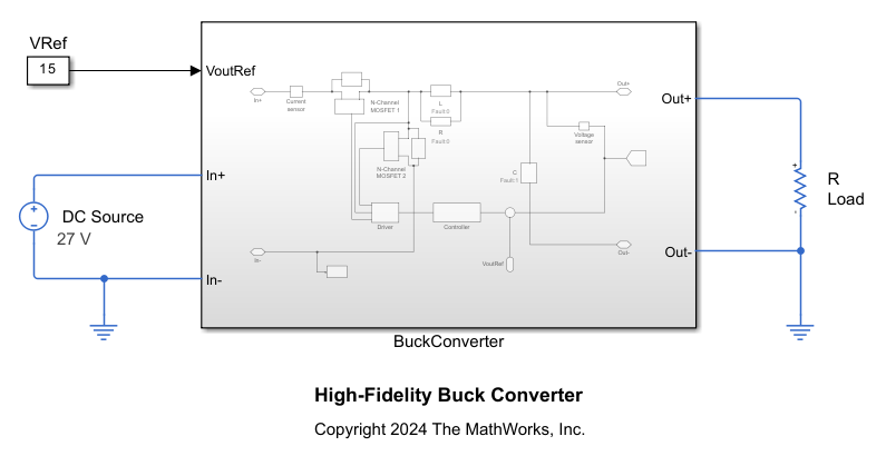
The BuckConverter subsystem models a buck converter by using two high-fidelity N-Channel MOSFET blocks. The subsystem also comprises a continuous PI controller and a driver. This motor drive has a nominal DC voltage of 486 V, a maximum shaft speed of 4000 RPM, and a rated torque of 90 Nm.
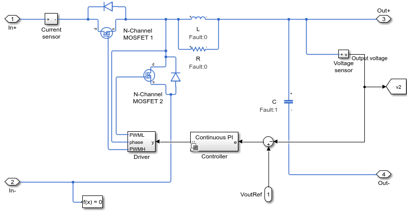
Ensure that the subsystem has the correct port names and port types. The subsystem must follow these rules:
The ports of the subsystem must match the ports of the DC-DC Converter block: In+, In-, Out+, Out-, and a Simulink input port for the output reference voltage.
The subsystem must be able to operate at nominal output conditions for rated power and output voltage and at the input voltage that you specify.
The subsystem must not include a DC voltage source on the input side.
The subsystem must include a capacitor on the output side.
The subsystem must not include a load on the output side.
Generate ROM
Run the generateDCDCConverterROM function to generate the ROM of the BuckConverter subsystem and set these options:
Specify the lookup table breakpoints for the input voltage and the output power.
Based on the model, the reference output voltage is 15 V.
To run simulations in parallel, set
UseParalleltotrue.Set the minimum simulation time of the generated test harness model to
0.003seconds.
generateDCDCConverterROM("HighFidelityBuckConverter/BuckConverter", ...
    InputVoltageBreakpoints=[27,30], ...
    ReferenceOutputVoltage=15, ...
    OutputPowerBreakpoints=[20:10:100], ...
    UseParallel=true, ...
    MinimumSimulationTime=0.003);
Starting parallel pool (parpool) using the 'Processes' profile ...
03-Dec-2025 15:39:17: Job Queued. Waiting for parallel pool job with ID 1 to start ...
Connected to parallel pool with 4 workers.
Using:
Reference voltage = 15 V
Input voltage breakpoints = [27;30] V
Output power breakpoints = [20;30;40;50;60;70;80;90;100] W
Maximum output power = 100 W
Auto-selected nominal operating conditions:
Using:
Reference voltage = 15 V
Input voltage breakpoints = [27 30] V
Output power breakpoints = [20 100] W
Validating harness initialization at nominal operating conditions ...
Load resistance values used = [11.25 2.25] Ohm
	Running iteration #1 : StopTimes = [0.003 0.003]sec
[03-Dec-2025 15:40:13] Checking for availability of parallel pool...
[03-Dec-2025 15:40:15] Starting Simulink on parallel workers...
[03-Dec-2025 15:40:58] Configuring simulation cache folder on parallel workers...
[03-Dec-2025 15:40:59] Loading model on parallel workers...
[03-Dec-2025 15:41:16] Running simulations...
[03-Dec-2025 15:42:03] Cleaning up parallel workers...
Computing voltage regulation time constant ...
	Running iteration #1 : StopTime = 0.006sec
Voltage regulation time constant = 3.6035e-05 seconds.
![Figure contains an axes object. The axes object with title Simulation Results for Voltage Regulation Time Constant Calculation Input DC Voltage = 30V Output Power = 100W, xlabel Time [s], ylabel Voltage [V] contains 3 objects of type line. These objects represent Voltage reference, Response, Fitted response (First order).](../../examples/simscapeelectrical/win64/GenerateBuckConverterSubsystemROMExample_03.png)
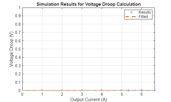
Successfully calculated voltage regulation time constant.
Computing voltage droop ...
Using:
Reference voltage = 15 V
Input voltage breakpoints = 30 V
Load resistance values used = [2.8125 2.5 2.25] Ohm
Power flows in Forward direction.
	Running iteration #1 : Stop times = [0.009 0.009 0.009]sec
[03-Dec-2025 15:42:51] Checking for availability of parallel pool...
[03-Dec-2025 15:42:51] Starting Simulink on parallel workers...
[03-Dec-2025 15:42:55] Configuring simulation cache folder on parallel workers...
[03-Dec-2025 15:42:55] Loading model on parallel workers...
[03-Dec-2025 15:42:59] Running simulations...
[03-Dec-2025 15:43:38] Cleaning up parallel workers...
	Running iteration #2 : Stop times = [0.0135 0.0135 0.0135]sec
[03-Dec-2025 15:43:43] Checking for availability of parallel pool...
[03-Dec-2025 15:43:43] Starting Simulink on parallel workers...
[03-Dec-2025 15:43:47] Configuring simulation cache folder on parallel workers...
[03-Dec-2025 15:43:47] Loading model on parallel workers...
[03-Dec-2025 15:43:50] Running simulations...
[03-Dec-2025 15:44:13] Cleaning up parallel workers...
	Running iteration #3 : Stop times = [0.018 0.018 0.018]sec
[03-Dec-2025 15:44:19] Checking for availability of parallel pool...
[03-Dec-2025 15:44:19] Starting Simulink on parallel workers...
[03-Dec-2025 15:44:21] Configuring simulation cache folder on parallel workers...
[03-Dec-2025 15:44:21] Loading model on parallel workers...
[03-Dec-2025 15:44:24] Running simulations...
[03-Dec-2025 15:44:46] Cleaning up parallel workers...
	Running iteration #4 : Stop times = [0.0225 0.0225 0.0225]sec
[03-Dec-2025 15:44:51] Checking for availability of parallel pool...
[03-Dec-2025 15:44:51] Starting Simulink on parallel workers...
[03-Dec-2025 15:44:53] Configuring simulation cache folder on parallel workers...
[03-Dec-2025 15:44:53] Loading model on parallel workers...
[03-Dec-2025 15:44:56] Running simulations...
[03-Dec-2025 15:45:20] Cleaning up parallel workers...
Calculated droop is smaller than the specified threshold of 1e-6 * Minimum load resistance used. Assuming zero voltage droop.
Voltage droop = 0 V/A.
Successfully calculated voltage droop.
Computing efficiency lookup table in Forward operating mode ...
Using:
Reference voltage = 15 V
Input voltage breakpoints = [27;30] V
Output power breakpoints = [20;30;40;50;60;70;80;90;100] W
[03-Dec-2025 15:45:28] Checking for availability of parallel pool...
[03-Dec-2025 15:45:28] Starting Simulink on parallel workers...
[03-Dec-2025 15:45:30] Configuring simulation cache folder on parallel workers...
[03-Dec-2025 15:45:30] Loading model on parallel workers...
[03-Dec-2025 15:45:33] Running simulations...
[03-Dec-2025 15:52:42] Cleaning up parallel workers...
Efficiency lookup table = [98.2140797068646 98.2021403460928;97.3567290542039 97.3466910968535;96.4913085560849 96.499242826151;95.5893364189801 95.6416568299956;94.8495096603386 94.8831117768724;94.1762703478253 94.2804445222016;93.5665598516723 93.7048302003892;92.9820065665367 93.1343487673715;92.3635238338073 92.5559711755897] %.
Input voltage vector for efficiency lookup table = [27;30] V.
Output current vector for efficiency lookup table = [1.33329282809648 1.33327671817913;1.99996497902051 2.00003517718409;2.66666147262163 2.66668416570261;3.33324464030948 3.33329607879341;3.99986811254931 3.99986157310064;4.66662487449426 4.66653946221402;5.33327468130336 5.33320203643591;5.9999318353769 5.99991425334112;6.66658640344189 6.66641270889268] A.
![Figure contains an axes object. The axes object with title Simulation Results for Power Conversion Efficiency Calculation Output Voltage Reference = 15V, xlabel Output Current [A], ylabel Efficiency [%] contains 2 objects of type line. These objects represent Input Vdc = 27V, Input Vdc = 30V.](../../examples/simscapeelectrical/win64/GenerateBuckConverterSubsystemROMExample_05.png)
Successfully calculated the efficiency lookup table.
Computing minimum input voltage required ...
Using:
Reference voltage = 15 V
Input voltage = 27 V
Output power breakpoints = 100 W
Minimum input voltage required for voltage regulation = 16.4139 V.
![Figure contains an axes object. The axes object with title Minimum Input Voltage Required for Voltage Regulation, xlabel Time [sec], ylabel Voltage [V] contains 3 objects of type line. These objects represent Output voltage, Input voltage.](../../examples/simscapeelectrical/win64/GenerateBuckConverterSubsystemROMExample_06.png)
Successfully calculated the minimum input voltage required for voltage regulation.
Running ROM harness model ...
Using:
Reference voltage = 15 V
Input voltage breakpoints = [27;30] V
Output power breakpoints = [20;30;40;50;60;70;80;90;100] W
[03-Dec-2025 15:55:14] Checking for availability of parallel pool...
[03-Dec-2025 15:55:14] Starting Simulink on parallel workers...
[03-Dec-2025 15:55:18] Configuring simulation cache folder on parallel workers...
[03-Dec-2025 15:55:18] Loading model on parallel workers...
[03-Dec-2025 15:55:22] Running simulations...
[03-Dec-2025 15:55:32] Cleaning up parallel workers...
Plotting voltage droop data for original model and ROM ...
![Figure contains an axes object. The axes object with title Simulation Results for Voltage Droop Calculation Original model vs. ROM, xlabel Load current [A], ylabel Voltage droop [V] contains 2 objects of type line. One or more of the lines displays its values using only markers These objects represent ROM, Original.](../../examples/simscapeelectrical/win64/GenerateBuckConverterSubsystemROMExample_07.png)
Plotting output voltage waveforms for original model and ROM at the maximum load and input voltage values you specified ...
![Figure contains an axes object. The axes object with title Output Voltage Waveforms Input Voltage = 30V Output Power = 100W Original model vs. ROM, xlabel Time [sec], ylabel Output Voltage [V] contains 2 objects of type line. These objects represent ROM, Original.](../../examples/simscapeelectrical/win64/GenerateBuckConverterSubsystemROMExample_08.png)
Plotting input current waveforms for original model and ROM ...
![Figure contains 2 axes objects. Axes object 1 with title Steady-state Input Current Waveforms Input Voltage = 27V Output Power = 20W Original model vs. ROM, xlabel Time [sec], ylabel Steady-state Input Current [A] contains 2 objects of type line. These objects represent ROM, Original. Axes object 2 with title Steady-state Input Current Waveforms Input Voltage = 30V Output Power = 20W Original model vs. ROM, xlabel Time [sec], ylabel Steady-state Input Current [A] contains 2 objects of type line. These objects represent ROM, Original.](../../examples/simscapeelectrical/win64/GenerateBuckConverterSubsystemROMExample_09.png)
![Figure contains 2 axes objects. Axes object 1 with title Steady-state Input Current Waveforms Input Voltage = 27V Output Power = 30W Original model vs. ROM, xlabel Time [sec], ylabel Steady-state Input Current [A] contains 2 objects of type line. These objects represent ROM, Original. Axes object 2 with title Steady-state Input Current Waveforms Input Voltage = 30V Output Power = 30W Original model vs. ROM, xlabel Time [sec], ylabel Steady-state Input Current [A] contains 2 objects of type line. These objects represent ROM, Original.](../../examples/simscapeelectrical/win64/GenerateBuckConverterSubsystemROMExample_10.png)
![Figure contains 2 axes objects. Axes object 1 with title Steady-state Input Current Waveforms Input Voltage = 27V Output Power = 40W Original model vs. ROM, xlabel Time [sec], ylabel Steady-state Input Current [A] contains 2 objects of type line. These objects represent ROM, Original. Axes object 2 with title Steady-state Input Current Waveforms Input Voltage = 30V Output Power = 40W Original model vs. ROM, xlabel Time [sec], ylabel Steady-state Input Current [A] contains 2 objects of type line. These objects represent ROM, Original.](../../examples/simscapeelectrical/win64/GenerateBuckConverterSubsystemROMExample_11.png)
![Figure contains 2 axes objects. Axes object 1 with title Steady-state Input Current Waveforms Input Voltage = 27V Output Power = 50W Original model vs. ROM, xlabel Time [sec], ylabel Steady-state Input Current [A] contains 2 objects of type line. These objects represent ROM, Original. Axes object 2 with title Steady-state Input Current Waveforms Input Voltage = 30V Output Power = 50W Original model vs. ROM, xlabel Time [sec], ylabel Steady-state Input Current [A] contains 2 objects of type line. These objects represent ROM, Original.](../../examples/simscapeelectrical/win64/GenerateBuckConverterSubsystemROMExample_12.png)
![Figure contains 2 axes objects. Axes object 1 with title Steady-state Input Current Waveforms Input Voltage = 27V Output Power = 60W Original model vs. ROM, xlabel Time [sec], ylabel Steady-state Input Current [A] contains 2 objects of type line. These objects represent ROM, Original. Axes object 2 with title Steady-state Input Current Waveforms Input Voltage = 30V Output Power = 60W Original model vs. ROM, xlabel Time [sec], ylabel Steady-state Input Current [A] contains 2 objects of type line. These objects represent ROM, Original.](../../examples/simscapeelectrical/win64/GenerateBuckConverterSubsystemROMExample_13.png)
![Figure contains 2 axes objects. Axes object 1 with title Steady-state Input Current Waveforms Input Voltage = 27V Output Power = 70W Original model vs. ROM, xlabel Time [sec], ylabel Steady-state Input Current [A] contains 2 objects of type line. These objects represent ROM, Original. Axes object 2 with title Steady-state Input Current Waveforms Input Voltage = 30V Output Power = 70W Original model vs. ROM, xlabel Time [sec], ylabel Steady-state Input Current [A] contains 2 objects of type line. These objects represent ROM, Original.](../../examples/simscapeelectrical/win64/GenerateBuckConverterSubsystemROMExample_14.png)
![Figure contains 2 axes objects. Axes object 1 with title Steady-state Input Current Waveforms Input Voltage = 27V Output Power = 80W Original model vs. ROM, xlabel Time [sec], ylabel Steady-state Input Current [A] contains 2 objects of type line. These objects represent ROM, Original. Axes object 2 with title Steady-state Input Current Waveforms Input Voltage = 30V Output Power = 80W Original model vs. ROM, xlabel Time [sec], ylabel Steady-state Input Current [A] contains 2 objects of type line. These objects represent ROM, Original.](../../examples/simscapeelectrical/win64/GenerateBuckConverterSubsystemROMExample_15.png)
![Figure contains 2 axes objects. Axes object 1 with title Steady-state Input Current Waveforms Input Voltage = 27V Output Power = 90W Original model vs. ROM, xlabel Time [sec], ylabel Steady-state Input Current [A] contains 2 objects of type line. These objects represent ROM, Original. Axes object 2 with title Steady-state Input Current Waveforms Input Voltage = 30V Output Power = 90W Original model vs. ROM, xlabel Time [sec], ylabel Steady-state Input Current [A] contains 2 objects of type line. These objects represent ROM, Original.](../../examples/simscapeelectrical/win64/GenerateBuckConverterSubsystemROMExample_16.png)
![Figure contains 2 axes objects. Axes object 1 with title Steady-state Input Current Waveforms Input Voltage = 27V Output Power = 100W Original model vs. ROM, xlabel Time [sec], ylabel Steady-state Input Current [A] contains 2 objects of type line. These objects represent ROM, Original. Axes object 2 with title Steady-state Input Current Waveforms Input Voltage = 30V Output Power = 100W Original model vs. ROM, xlabel Time [sec], ylabel Steady-state Input Current [A] contains 2 objects of type line. These objects represent ROM, Original.](../../examples/simscapeelectrical/win64/GenerateBuckConverterSubsystemROMExample_17.png)
Plotting efficiency lookup data for original model and ROM ...
![Figure contains an axes object. The axes object with title Simulation Results for Power Conversion Efficiency Calculation Original model vs. ROM, xlabel Output Current [A], ylabel Efficiency [%] contains 4 objects of type line. One or more of the lines displays its values using only markers These objects represent Input Vdc = 27V - Original, Input Vdc = 30V - Original, Input Vdc = 27V - ROM, Input Vdc = 30V - ROM.](../../examples/simscapeelectrical/win64/GenerateBuckConverterSubsystemROMExample_18.png)
Successfully plotted results for original model and new ROM.
ROM generation complete.
Input Arguments
Name-Value Arguments
Output Arguments
Limitations
The generated ROM does not include high-order dynamics. If your model must represent high-order dynamic behaviors, do not replace the original system.
The
generateDCDCConverterROMfunction only loads these variables into the harness model workspace:Variables that you specify inside the
PreLoadFcnandPostLoadFcnmodel callbacks of your original modelVariables inside the model workspace of your original model
If the blocks of your model uses variables in the
InitFcnmodel callback, this function returns an invalid parameter name error when simulating the harness model. For more information about model callbacks, see Model Callbacks.