Debug Run-Time Errors in a State Transition Table
A state transition table represents a finite state machine for sequential modal logic in tabular format. Instead of drawing states and transitions in a Stateflow® chart, you can use a state transition table to model a state machine in a concise, compact format that requires minimal maintenance of graphical objects. For more information, see Model Finite State Machines Using State Transition Tables.
Create the Model and the State Transition Table
Create a Simulink® model with a new State Transition Table.
sfnew -STTAdd the following states and transitions to your table:
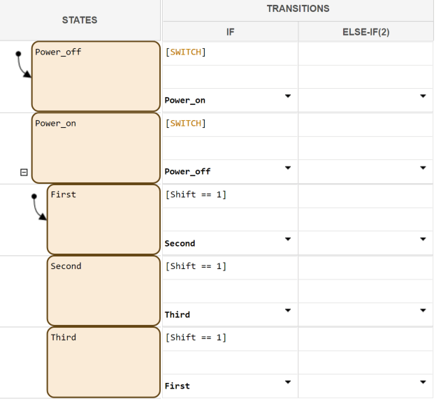
The table has two states at the highest level in the hierarchy,
Power_offandPower_on. By default,Power_offis active. The eventSWITCHtoggles the system between thePower_offandPower_onstates.Power_onhas three substates:First,Second, andThird. By default, whenPower_onbecomes active,Firstalso becomes active. WhenShiftequals 1, the system transitions fromFirsttoSecond,SecondtoThird, andThirdtoFirst, for each occurrence of the eventSWITCH. Then the pattern repeats.Add two inputs from Simulink:
An event called
SWITCHwith a scope of Input from Simulink and a Rising edge trigger.A data called
Shiftwith a scope of Input from Simulink.
In the model view, connect a Sine Wave block as the
SWITCHevent and a Step block as theShiftdata for your State Transition Table.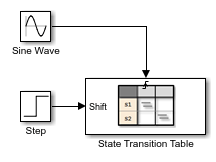
In the model, there is an event input and a data input. A Sine Wave block generates a repeating input event that corresponds with the Stateflow event
SWITCH. The Step block generates a repeating pattern of 1 and 0 that corresponds with the Stateflow data objectShift. Ideally, theSWITCHevent occurs at a frequency that allows at least one cycle throughFirst,Second, andThird.
Debug the State Transition Table
To debug the table in Create the Model and the State Transition Table, follow these steps:
Right-click the
Power_offstate, and select Set Breakpoint > On State Entry.Start the simulation.
Because you specified a breakpoint on
Power_off, execution stops at that point.Move to the next step by clicking the Step In button,
 .
.To see the data used and the current values, hover your cursor over the different table cells.
Continue clicking the Step In button and watching the animating states. After each step, watch the chart animation to see the sequence of execution. Use the tooltips to see the data values.
Single-stepping shows that the loop from First to
Second to Third inside the state
Power_on does not occur. The transition from
Power_on to Power_off takes
priority.
Correct the Run-Time Error
In Debug the State Transition Table, you step through a simulation of a
state transition table and find an error. The event SWITCH drives
the simulation, but the simulation time passes too quickly for the input data object
Shift to have an effect.
To correct this error:
Stop the simulation so that you can edit the table.
Add the condition
after(20.0, sec)to the transition fromPower_ontoPower_off.
Now the transition from
Power_ontoPower_offdoes not occur until 20 seconds have passed.Begin simulation.
Click the Step In button repeatedly to observe the fixed behavior.